Kia Cadenza YG: Windshield Wiper/Washer / Front Wiper Motor Repair procedures
| Removal |
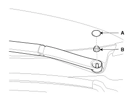
| 1. |
Loosen the windshield wiper arm nut (B) after removing a wiper cap (A).
|
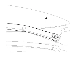
| 2. |
Remove the windshield wiper arm and blade (A).
|
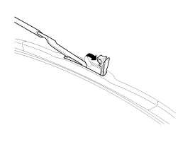
| 3. |
If necessary, release the wiper blade fixing clip by pulling up and remove the wiper blade from the inside radius of wiper arm.
|
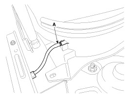
| 4. |
Disconnect the washer hose (A) connected to cowl top cover.
|
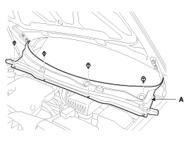
| 5. |
Remove the weather strip and the cowl top cover (A) after removing rivets.
|
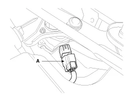
| 6. |
Disconnect the wiper motor connector (A) from the wiper motor & linkage assembly.
|
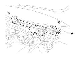
| 7. |
Remove the windshield wiper motor and linkage assembly (A) after removing 2 bolts.
|
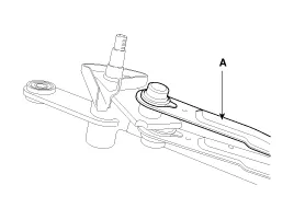
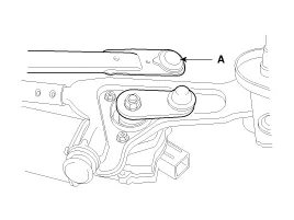
| 8. |
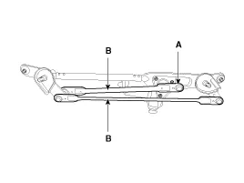
Hold the wiper motor crank arm and remove the upper linkage (A) from the wiper motor crank arm.
|

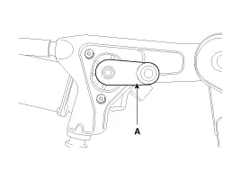
| 9. |
Remove the lower linkage (A) from the wiper motor crank arm.
|
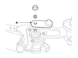
| 10. |
Remove the crank arm (A) after loosening a nut.
|
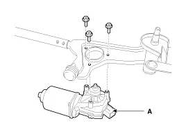
| 11. |
Remove the wiper motor (A) after loosening the bolts.
|
| Installation |
| 1. |
Install the wiper motor. |
| 2. |
Install the crank arm.
|
| 3. |
Install the lower and upper linkage to the wiper motor crank arm. |
| 4. |
Install the wiper motor and linkage assembly and then connect the wiper motor connector.
|
| 5. |
Install the cowl top cover. |
| 6. |
Install the windshield wiper arm and blade.
|

| 7. |
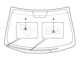
Install the wiper arm and blade to the specified position.
A : Auto stop position (Blade)
|
| 8. |
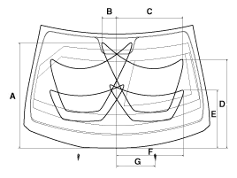
Set the cowl top cover on the specified spray position.
|
| Inspection |
| 1. |
Remove the connector (A) from the wiper motor.
|
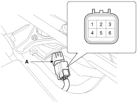
| 2. |
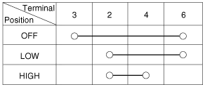
Attach the positive (+) lead from the battery to terminal 2 and the negative (-) lead to terminal 5. |
| 3. |
Check that the motor operates at low or high speed as below table.
|
Component Location 1. Cap2. Nut3. Wiper arm & blade4. Rivet5. Cowl top cover6. Bolt7. Wiper motor & linkage assembly
Inspection 1. With the washer motor connected to the reservoir tank, fill the reservoir tank with water. Before filling the reservoir tank with water, check the filter for foreign material or contamination.
Other information:
Kia Cadenza YG 2016-2021 Service Manual: Surround View Monitoring Switch Repair procedures
Removal 1. Disconnect the negative (-) battery terminal. 2. Remove the floor console upper cover. (Refer to Body - "Floor Console Assembly") 3. Disconnect the console upper cover connector (A). 4. Remove the cup holder assembly (A) after loosening the mounting screws.
Kia Cadenza YG 2016-2021 Service Manual: Compressor Repair procedures
Removal 1. If the compressor is marginally operable, run the engine at idle speed, and let the air conditioning work for a few minutes, then shut the engine off. 2. Disconnect the negative cable from the battery. 3. Recover the refrigerant with a recovery/charging station.
Categories
- Manuals Home
- Kia Cadenza Owners Manual
- Kia Cadenza Service Manual
- Components and Components Location
- Emission Control System
- Battery Troubleshooting
- New on site
- Most important about car
