Kia Cadenza YG: Automatic Transaxle Control System / Inhibitor Switch Schematic Diagrams
Kia Cadenza YG 2016-2021 Service Manual / Automatic Transaxle System / Automatic Transaxle Control System / Inhibitor Switch Schematic Diagrams
| Circuit Diagram |
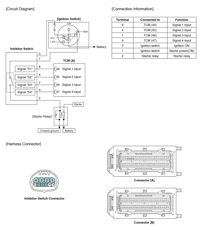
Specifications ▷ Type: Combination of output signals from 4 terminals ▷ Specifications Power supply (V)12Output typePin to Pin ▷ Signal Code Table PP-RRR-NNN-DDS112V12V00000S2012V12V12V000S300012V12V12V0S40000012V12V
Inspection • Thoroughly check connectors for looseness, poor connection, bending, corrosion, contamination, deterioration, or damage.
Other information:
Kia Cadenza YG 2016-2021 Service Manual: Components and Components Location
C
Kia Cadenza YG 2016-2021 Service Manual: Blind Spot Detection Unit Repair procedures
Removal 1. Disconnect the negative (-) battery terminal. 2. Remove the rear bumper. (Refer to Body - "Rear Bumper") 3. Remove the BSD unit (A) after loosening the mounting screws. Take care not to separate the bracket from rear bumper when removing the BSD sensor.
Categories
- Manuals Home
- Kia Cadenza Owners Manual
- Kia Cadenza Service Manual
- Steering System
- Specifications
- Brake System
- New on site
- Most important about car

Copyright © 2026 www.kcadenzavg.com - 0.0284