Kia Cadenza YG: Engine Control System / Injector Repair procedures
Kia Cadenza YG 2016-2021 Service Manual / Engine Control / Fuel System / Engine Control System / Injector Repair procedures
| Inspection |
| 1. |
Turn the ignition switch OFF. |
| 2. |
Disconnect the injector connector. |
| 3. |
Measure resistance between the injector terminals 1 and 2. |
| 4. |
Check that the resistance is within the specification.
|
| Removal |
In case of removing the high pressure fuel pump, high
pressure fuel pipe, delivery pipe, and injector, there may be injury
caused by leakage of the high pressure fuel. So don’t do any repair
work right after engine stops.
|

| 1. |
Turn the ignition switch OFF and disconnect the battery negative (-) cable. |
| 2. |
Release the residual pressure in fuel line.
(Refer to the Fuel Delivery System - Repair Procedures - "Release Residual Pressure in Fuel Line").
|

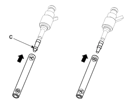
| 3. |
Remove the delivery pipe & injector assembly.
(Refer to Fuel Delivery System - “Delivery Pipe”) |
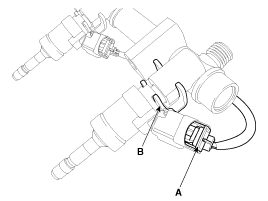
| 4. |
Remove the connector (A) and the fixing clip (B), and then separate the injector from the delivery pipe.
|
| Installation |
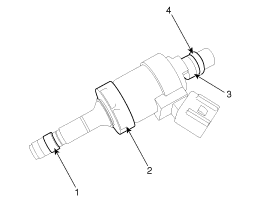
| 1) |
Combustion seal |
| 2) |
Rubber washer |
| 3) |
Support disc |
| 4) |
O-ring
|
|
|
|
|
|
|
|
| 1. |
Install in the reverse order of removal. |
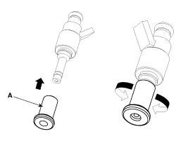
| Replacement |
The injector combustion seal should be replaced new one to prevent leakage after removing the injector.
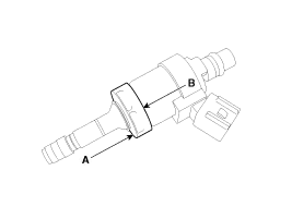
| 1. |
Remove the combustion seal (A) with a wire cutter.
|

| 2. |
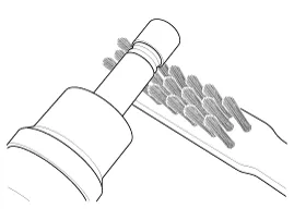
Before the assembly of the sealing ring the groove must be cleaned using a clean cloth.
Any coking of the injector sealing surface must be carefully removed with a brass-wire brush.
|
| 3. |
Place the seal installing guide (B) (SST No.: 09353-2B000) on the tip of the injector not to damage the injector tip (A).
Push the sealing ring (C) with thumb and index finger over the conical assembly tool until it snaps into the groove.
The complete assembly must not take longer than 2 to 3 seconds.
|

| 4. |
To size the sealing ring the injector is first introduced
into the sizing tool (A) (SST No.: 09353-2B000) and then pressed and at
the same time rotated 180° into the sizing tool.
|
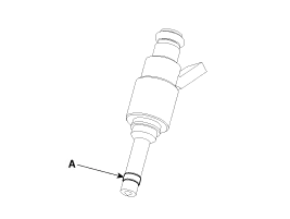
| 5. |
Pull the injector out of the sizing tool by turning it in the reverse direction to that used for the press-in process.
|
| 6. |
Check the combustion seal (A) installation.
|
Circuit Diagram
Description Purge Control Solenoid Valve (PCSV) is installed on the surge tank and controls the passage between the canister and the intake manifold.
Other information:
Kia Cadenza YG 2016-2021 Service Manual: Description and Operation
System Overview RPAS (Rear Parking Assist System) is an electronic driving aid that warns the driver to be cautious while parking or in low speed environments. The sensor uses ultrasonic waves to detect objects within proximity of the vehicle.
Kia Cadenza YG 2016-2021 Service Manual: Schematic Diagrams
C
Categories
- Manuals Home
- Kia Cadenza Owners Manual
- Kia Cadenza Service Manual
- Timing Chain Repair procedures
- Specifications
- Alternator Schematic Diagrams
- New on site
- Most important about car

Copyright © 2026 www.kcadenzavg.com - 0.0199