Kia Cadenza YG: Automatic Transaxle Control System / Input Speed Sensor Repair procedures
| Inspection |
| 1. |
Turn ignition switch OFF. |
| 2. |
Remove the battery and battery tray.
(Refer to Engine Electrical System - "Battery") |
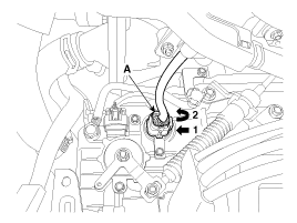
| 3. |
Disconnect the solenoid valve connector (A).
|
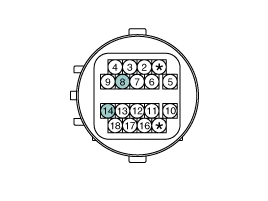
| 4. |
Measure the resistance between power terminal (14) and signal terminal (8).
|
| Removal |
| 1. |
Remove the valve body assembly.
(Refer to Hydraulic System - "Valve Body") |
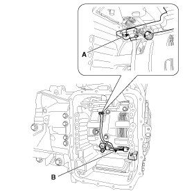
| 2. |
Disconnect the input & output speed sensor connector (A). |
| 3. |
Remove the input & output speed sensor (B) after loosening the bolts.
|
| Installation |
| 1. |
Install in the reverse order of removal.
|

Signal Waveform Fig 1) Input/Output speed sensor at low speed Fig 2) Input/Output speed sensor at high speed
Description The output speed sensor is a vital unit that measures the rate of rotation of the transaxle''s turbine shaft and output shaft, and delivers the readings to the Transaxle Control Module(TCM).
Other information:
Kia Cadenza YG 2016-2021 Service Manual: Ambient Sensor Description and Operation
Description 1. The ambient temperature sensor is located at the front of the condenser and detects ambient air temperature. It is a negative type thermistor resistance will increase with lower temperature, and decrease with higher temperatures.
Kia Cadenza YG 2016-2021 Service Manual: Blower Unit Repair procedures
Replacement 1. Disconnect the negative (-) battery terminal. 2. Remove the heater and blower unit.(Refer to HA group – heater unit). 3. Remove the blower unit (A) from the heater unit after loosening a mounting bolt and 3 screws. Make sure that there is no air leaking out of the blower and duct joints.
Categories
- Manuals Home
- Kia Cadenza Owners Manual
- Kia Cadenza Service Manual
- Timing Chain Repair procedures
- General Information
- Suspension System
- New on site
- Most important about car
