Kia Cadenza YG: Panoramaroof / Panoramaroof Motor Repair procedures
Kia Cadenza YG 2016-2021 Service Manual / Body Electrical System / Panoramaroof / Panoramaroof Motor Repair procedures
| Inspection |
| 1. |
Disconnect the negative (-) battery terminal. |
| 2. |
Remove the roof trim.
(Refer to Body - "Roof Trim") |
| 3. |
Disconnect the panoramaroof motor (A) connector.
|
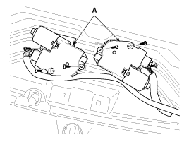
| 4. |
Ground the terminals as below table, and check that the panoramaroof unit operates.
|

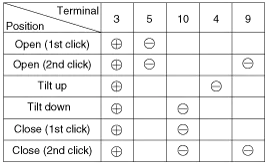
| 5. |
Make these input tests at the connector. If any test
indicates a problem, find and correct the cause, then recheck the
system. If all the input tests prove OK, the panoramaroof motor must be
faulty; replace it.
|
| 6. |
Ground the terminals as below table, and check that the roller blind motor operates.
|

| Resetting The Panoramaroof |
Whenever the vehicle battery is disconnected or discharged,
or you use the emergency handle to operate the panoramaroof, you have to
reset your panoramaroof system as follows :
| 1. |
Turn the ignition key to the ON position and then close the panoramaroof completely. |
| 2. |
Release the panoramaroof control lever. |
| 3. |
Press and hold the CLOSE button for more than 10 seconds until the panoramaroof has moved slightly. |
| 4. |
Release the panoramaroof control lever. |
| 5. |
Press and hold the CLOSE button once again within 3 seconds until the panoramaroof do as follows;
|
| 6. |
Reset procedure of panorama system is finished. |
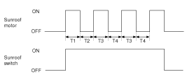
Protecting Motor From Overheating
In order to protect the panoramaroof motor from overheating
from continuous motor operation, the panoramaroof ECU controls the
Run-time and Cool-time of the motor as follows:
| 1. |
The panoramaroof ECU detects the Run- time of motor |
| 2. |
Motor can be operated continuously for the 1st run-time(120 ± 10sec.). |
| 3. |
The continuous operation of motor stops after the 1st Run-time(120 ± 10sec.). |
| 4. |
Then Motor is not operated for the 1st Cool-time(18 ± 2sec.). |
| 5. |
Motor is operated for the 2nd Run-time(10 ± 2sec.) at the continued motor operation after 1st Cool-time(18 ± 2sec.) |
| 6. |
The continuous operation of motor stops operating after the 2nd Run-time(10 ± 2sec.) |
| 7. |
Motor is not operated for the 2nd Cool-time(18 ± 2sec.). |
| 8. |
Motor repeats the 2nd run-time and 2nd cool-time at the continued motor operation.
T1 : 120 ± 10 sec., T2 : 18 ± 2 sec.,
T3 : 10 ± 2 sec., T4 : 18 ± 2 sec. |
Inspection 1. Disconnect the negative (-) battery terminal. 2. Remove the overhead console lamp assembly. (Refer to Body - "Roof Trim") 3. Check for continuity between the terminals.
Other information:
Kia Cadenza YG 2016-2021 Service Manual: Start/Stop Button Repair procedures
Removal 1. Disconnect the negative (-) battery terminal. 2. Using a screw driver or remover, remove the center fascia lower panel (A). 3. Remove the in-car hose (A) and disconnect the connectors (B) from the heater & A/C control unit. 4.
Kia Cadenza YG 2016-2021 Service Manual: Repair procedures
Diagnosis With GDS 1. BSD system defects can be quickly diagnosed with the GDS. GDS operates actuator quickly to monitor, input/output value and self diagnosis. 2. Connect the cable of GDS to the data link connector in driver side crash pad lower panel, turn the power on GDS.
Categories
- Manuals Home
- Kia Cadenza Owners Manual
- Kia Cadenza Service Manual
- Restraint
- Alternator Schematic Diagrams
- Engine Electrical System
- New on site
- Most important about car

Copyright © 2026 www.kcadenzavg.com - 0.0256