Kia Cadenza YG: Fuses And Relays / Relay Box (Engine Compartment) Repair procedures
Kia Cadenza YG 2016-2021 Service Manual / Body Electrical System / Fuses And Relays / Relay Box (Engine Compartment) Repair procedures
| Inspection |
Power Relay Test (Type A)
|

Check for continuity between the terminals.
| A. Front deicer B. IGN2 relay C. Blower relay D. Burglar alarm horn relay E. IGN1 relay F. Cooling fan #1 relay | G. Cooling fan #2 relay H. Start relay I. Rear defogger J. Horn relay K. ACC relay L. Fuel pump relay |
| 1. |
There should be continuity between the No.30 and No.87
terminals when power and ground are connected to the No.85 and No.86
terminals. |
| 2. |
There should be no continuity between the No.30 and No.87 terminals when power is disconnected.
|


Power Relay Test (Type B)
Check for continuity between the terminals.
A : Rain sensor relay
B : Wiper relay
| 1. |
There should be continuity between the No.30 and No.87
terminals when power and ground are connected to the No.85 and No.86
terminals. |
| 2. |
There should be continuity between the No.30 and No.87 terminals when power is disconnected.
|

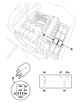
Power Relay Test (Type C)
Check for continuity between the terminals.
A : ECU relay
| 1. |
There should be continuity between the No.30, 87a and No.87
terminals when power and ground are connected to the No.85 and No.86
terminals. |
| 2. |
There should be no continuity between the No.30, 87a and No.87 terminals when power is disconnected.
|


Fuse Inspection
| 1. |
Be sure there is no play in the fuse holders, and that the fuses are held securely. |
| 2. |
Are the fuse capacities for each circuit correct? |
| 3. |
Are there any blown fuses?
If a fuse is to be replaced, be sure to use a new fuse of the
same capacity. Always determine why the fuse blew first and completely
eliminate the problem before installing a new fuse. |
Multi Fuse
Multi Fuse is for optimizing the engine room package.

|
Categories
- Manuals Home
- Kia Cadenza Owners Manual
- Kia Cadenza Service Manual
- Suspension System
- Engine Control / Fuel System
- Brake System
- New on site
- Most important about car

Copyright © 2026 www.kcadenzavg.com - 0.0341