Kia Cadenza YG: Smart key System / Repair procedures
| Inspection |
| 1. |
Problem in SMART KEY unit input. |
| 2. |
Problem in SMART KEY unit. |
| 3. |
Problem in SMART KEY unit output. |
| 1. |
SMART KEY unit Input problem : switch diagnosis |
| 2. |
SMART KEY unit problem : communication diagnosis |
| 3. |
SMART KEY unit Output problem : antenna and switch output diagnosis |
| 1. |
Connect the cable of GDS to the data link connector in driver side crash pad lower panel, turn the power on GDS. |
| 2. |
Select the vehicle model and then SMART KEY system.
|
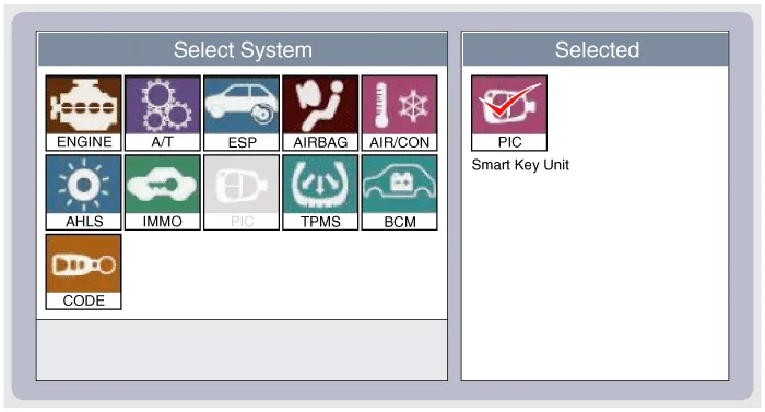
| 3. |
Select the "SMART KEY unit". |
| 4. |
After IG ON, select the "Current data".
|

| 5. |
You can see the situation of each switch on scanner after connecting the "current data" process.
|
| 1. |
Communication diagnosis checks that the each linked components operates normal. |
| 2. |
Connect the cable of GDS to the data link connector in driver side crash pad lower panel. |
| 3. |
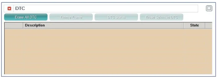
After IG ON, select the "DTC".
|
| 1. |
Connect the cable of GDS to the data link connector in driver side crash pad lower panel. |
| 2. |
After IG ON, select the "ACTUATION TEST".
|
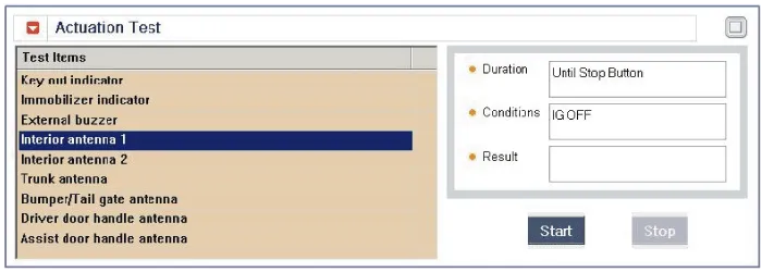
| 3. |
Set the smart key near the related antenna and operate it with a GDS.
|
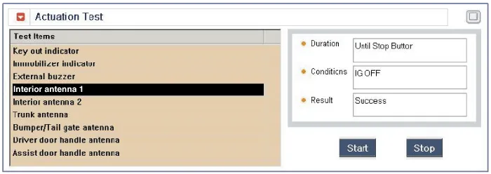
| 4. |
If the LED of smart key is blinking, the smart key is normal. |
| 5. |
If the LED of smart key is not blinking, check the voltage of smart key battery. |
| 6. |
Antenna actuation
|
| 1. |
Connect the cable of GDS to the data link connector in driver side crash pad lower panel. |
| 2. |
Select the "Antenna Status Check".
|
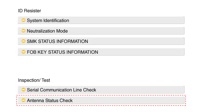
| 3. |
After IG ON, select the "Antenna Status Check".
|
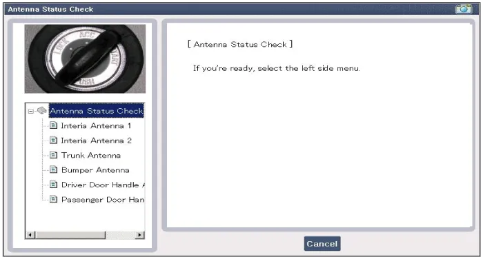
| 4. |
Set the smart key near the related antenna and operate it with a GDS.
|
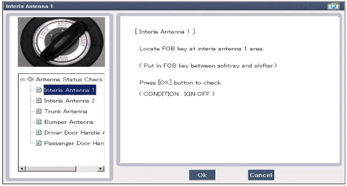
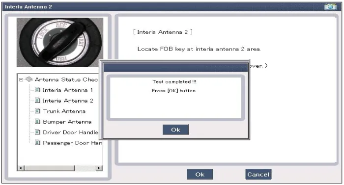
| 5. |
If the smart key runs normal , the related antenna, smart key(transmission, reception) and exterior receiver are normal. |
| 6. |
Antenna status
|
| 1. |
Connect the cable of GDS to the data link connector in driver side crash pad lower panel. |
| 2. |
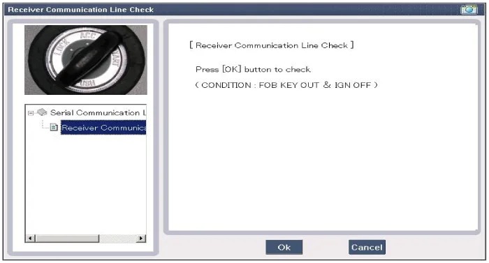
Select the "Serial Communication Line Check".
|
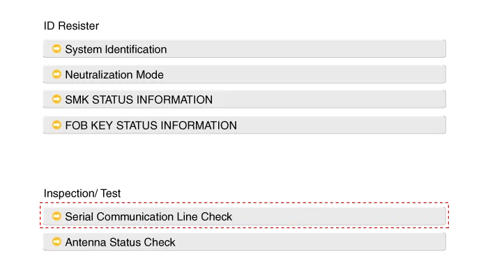
| 3. |
After IGN ON, select the "Receiver Communication Line Check".
|
| 4. |
Check the serial communication line with a GDS. |
| 5. |
If the smart key runs normal, the communication of smart key unit, exterior receiver and ESCL are normal. |
| 6. |
If the smart key runs abnormal, check the following items.
|
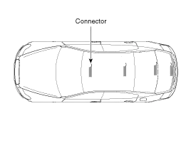
| 1. |
Set the smart key in the following shade area and check the IG ON.
|
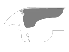
| 2. |
If the ignition is ON, the antenna runs normal. |
| 3. |
Check the interior antenna ignition mode. |
| 4. |
Set the smart key in the following shade area and actuate the antenna. Check the LED of smart key is blinking.
|
| 5. |
If the LED of smart key is not blinking, check the antenna in shade area.
|
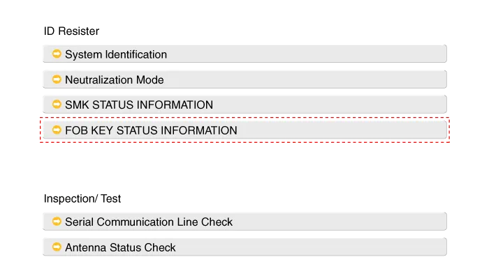
| 1. |
Connect the cable of GDS to the data link connector in driver side crash pad lower panel. |
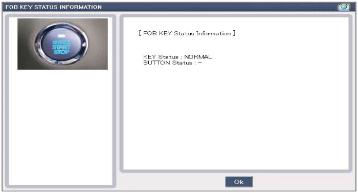
| 2. |
After IGN ON, select the "FOB KEY STATUS INFO".
|
| 1. |
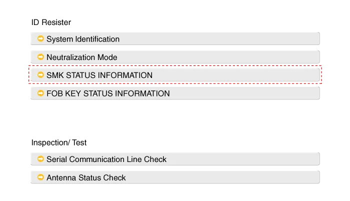
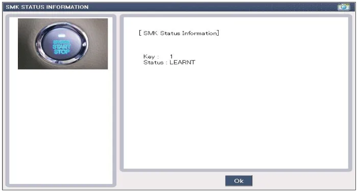
Connect the cable of GDS to the data link connector in driver side crash pad lower panel. |
| 2. |
After IG ON, select the "SMK STATUS INFO".
|
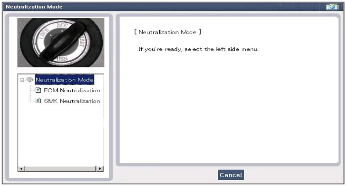
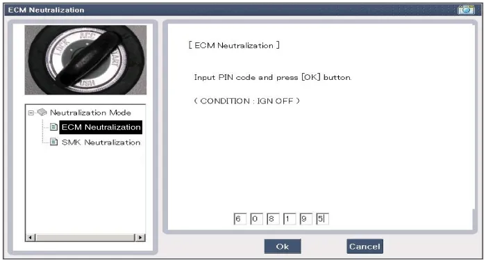
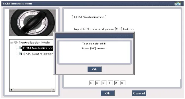
| 1. |
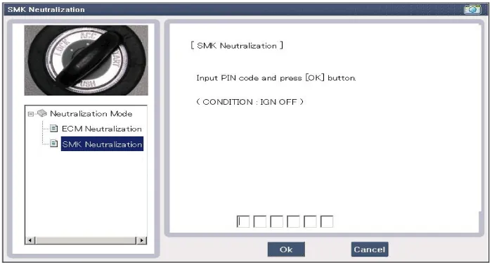
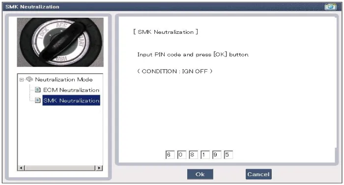
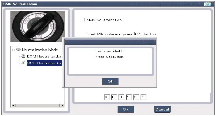
Connect the cable of GDS to the data link connector in driver side crash pad lower panel. |
| 2. |
After IGN ON, select the "Neutralization mode".
|

| No | Item name | Unit |
| 1 | SSB switch2 | - |
| 2 | ACC | - |
| 3 | IGN1 | - |
| 4 | Gear ''P'' Position | - |
| 5 | Brake switch | - |
| 6 | FL Door Lock Button | - |
| 7 | FR Door Lock Button | - |
| 8 | Trunk Lid switch | - |
| 9 | Battery Voltage | - |
| 10 | Alternator Voltage | - |
| 11 | KEY out Indicator Lamp | - |
| 12 | Immobilizer Lamp | - |
| 13 | External Buzzer | - |
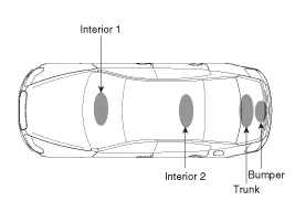
| No. | Item name | Condition |
| 1 | Immo.indicator Lamp | Ignition switch ON Engine off |
| 2 | External Buzzer | Ignition switch ON Engine off |
| 3 | Interior Antenna 1 Active | Ignition switch ON Engine off |
| 4 | Interior Antenna 2 Active | Ignition switch ON Engine off |
| 5 | Trunk Antenna Active | Ignition switch ON Engine off |
| 6 | Bumper Antenna Active | Ignition switch ON Engine off |
| 7 | DRV DR Antenna Active | Ignition switch ON Engine off |
| 8 | AST DR Antenna Active | Ignition switch ON Engine off |
Description The SMART KEY system is a system that allows the user to access and operate a vehicle in a very convenient way. To access the vehicle, no traditional key or remote control unit is needed.
Smart Key Smart Key Code Saving 1. Connect the DLC cable of GDS to the data link connector in driver side crash pad lower panel, turn the power on GDS.
Other information:
Kia Cadenza YG 2016-2021 Service Manual: Description and Operation
Description BSD is a system that uses two magnetic wave radar sensors attached on the rear bumper to measure the distance from the following vehicles and provides the sensing and (visual and auditory) alarm of any vehicle coming into the blind spot.
Kia Cadenza YG 2016-2021 Service Manual: Photo Sensor Repair procedures
Inspection 1. Ignition "ON" 2. Using the scan tool. 3. Emit intensive light toward photo sensor using a lamp, and check the output voltage change. 4. The voltage will rise with higher intensive light and reduce with lower intensive light.
Categories
- Manuals Home
- Kia Cadenza Owners Manual
- Kia Cadenza Service Manual
- Body (Interior and Exterior)
- Battery Troubleshooting
- General Information
- New on site
- Most important about car
