Kia Cadenza YG: Keyless Entry And Burglar Alarm / Repair procedures
| Inspection |
| 1. |
Remove the front door trim.
(Refer to Body - "Front Door") |
| 2. |
Remove the front door module. |
| 3. |
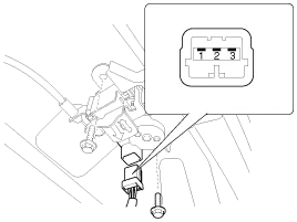
Disconnect the 6P connector from the actuator.
|
| 4. |
Check actuator operation by connecting power and ground
according to the table. To prevent damage to the actuator, apply battery
voltage only momentarily.
|
| 1. |
Remove the rear door trim.
(Refer to Body - "Rear Door") |
| 2. |
Remove the rear door module. |
| 3. |
Disconnect the 6P connector from the actuator.
|
| 4. |
Check actuator operation by connecting power and ground
according to the table. To prevent damage to the actuator, apply battery
voltage only momentarily.
|
| 1. |
Remove the trunk lid trim panel.
(Refer to Body - "Trunk Lid") |
| 2. |
Disconnect the 3P connector from the actuator.
|
| 3. |
Check actuator operation by connecting power and ground
according to the table. To prevent damage to the actuator, apply battery
voltage only momentarily.
|

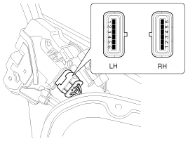
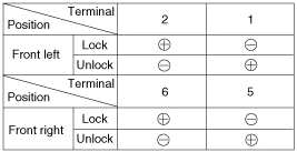
| 1. |
Remove the front door trim panel.
(Refer to Body - "Front Door") |
| 2. |
Remove the front door module. |
| 3. |
Disconnect the 6P connector from the actuator.
|
| 4. |
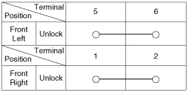
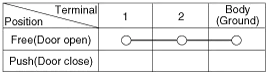
Check for continuity between the terminals in each switch position when inserting the key into the door according to the table.
|
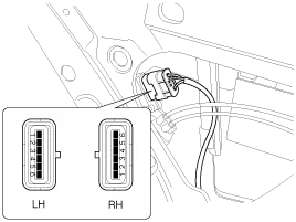
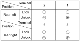
| 1. |
Remove the rear door trim panel.
(Refer to Body - "Rear Door") |
| 2. |
Remove the rear door module. |
| 3. |
Disconnect the 6P connector from the actuator.
|
| 4. |
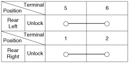
Check for continuity between the terminals in each switch position according to the table.
|
| 1. |
Remove the trunk lid trim.
(Refer to Body - "Trunk Lid") |
| 2. |
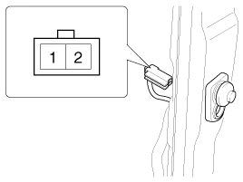
Disconnect the 3P connector from the actuator.
|
| 3. |
Check for continuity between the terminals in each switch position according to the table.
|

| 1. |
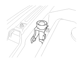
Disconnect the connector from the hood switch (A).
|
| 2. |
Check for continuity between the terminals and ground according to the table.
|

| 1. |
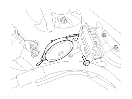
Remove the burglar horn (A) after removing 1 bolt and disconnect the 2P connector from the burglar horn.
|
| 2. |
Test the burglar horn by connecting battery power to the terminal 1 and ground the terminal 2. |
| 3. |
The burglar horn should make a sound. If the burglar horn fails to make a sound replace it. |
Description Burglar Alarm State [B/A State] B/A StateDescriptionDISARM 1) In "DISARM" state, no vehicle start inhibition. So, when door, hood, or Tailgate is opened, there is no alarm sound and flashing.
Inspection 1. Check that the red light flickers when the door lock or unlock button is pressed on the transmitter. 2. Remove the battery (A) and check voltage if the red light doesn''t flicker.
Other information:
Kia Cadenza YG 2016-2021 Service Manual: A/C Pressure Transducer Description and Operation
Description A/C pressure transducer convert the pressure value of high pressure line into voltage value after measure it. By converted voltage value, engine ECU controls cooling fan by operating it high speed or low speed. Engine ECU stop the operation of compressor when the temperature of refrigerant line is so high or so low irregularl
Kia Cadenza YG 2016-2021 Service Manual: A/C Pressure Transducer Repair procedures
Inspection 1. Measure the pressure of high pressure line by measuring voltage output between NO.1 and NO.2 terminals. 2. Inspect the voltage value whether it is sufficient to be regular value or not. Voltage = 0.00878835 * Pressure + 0.37081095 [PSIA] 3.
Categories
- Manuals Home
- Kia Cadenza Owners Manual
- Kia Cadenza Service Manual
- Body (Interior and Exterior)
- Steering System
- Transaxle Control Module (TCM) Repair procedures
- New on site
- Most important about car
