Kia Cadenza YG: Lighting System / Room Lamp Repair procedures
| Inspection |
| 1. |
Check that the switch operates properly after disconnecting the room lamp connector (A).
|


| Removal |
| 1. |
Disconnect the negative(-) battery terminal. |
| 2. |
Carefully remove the lens (A) using a small screwdriver.
|

| 3. |
Remove the bulb (A) and room lamp after loosening the mounting screws.
|

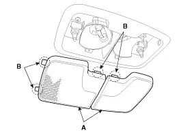
| 4. |
Remove the room lamp assembly (A) from the head lining after disconnecting the connector (B).
|

| 1. |
Disconnect the negative (-) battery terminal. |
| 2. |
Remove the vanity lamp (A) by pressing the clip (B) with a flat-tip screwdriver.
|

| 3. |
Replace the bulb. |
| Installation |
| 1. |
Reconnect the connector. |
| 2. |
Install the room lamp assembly. |
| 3. |
Install the lens. |
| 1. |
Reconnect the vanity lamp connector. |
| 2. |
Install the vanity lamp. |
Inspection 1. Check-points upon head lamp failure (HID) (1) Check the battery voltage. (Low beam will be on when the battery voltage above 9V.) (2) Check the fuse and relay.
Inspection Overhead Console Lamp Remove the overhead console lamp assembly then check for continuity between terminals. If the continuity is not as specified, replace the map lamp switch.
Other information:
Kia Cadenza YG 2016-2021 Service Manual: Compressor Repair procedures
Removal 1. If the compressor is marginally operable, run the engine at idle speed, and let the air conditioning work for a few minutes, then shut the engine off. 2. Disconnect the negative cable from the battery. 3. Recover the refrigerant with a recovery/charging station.
Kia Cadenza YG 2016-2021 Service Manual: Ambient Sensor Repair procedures
Inspection 1. Ignition "OFF" 2. Disconnect ambient temperature sensor. 3. Check the resistance of ambient temperature sensor between terminals 1 and 2 whether it is changed by changing of the ambient temperature. 1. Sensor Ground2.
Categories
- Manuals Home
- Kia Cadenza Owners Manual
- Kia Cadenza Service Manual
- Specifications
- Emission Control System
- Restraint
- New on site
- Most important about car
