Kia Cadenza YG: Cruise Control System / Schematic Diagrams
Kia Cadenza YG 2016-2021 Service Manual / Engine Electrical System / Cruise Control System / Schematic Diagrams
| System Block Diagram |
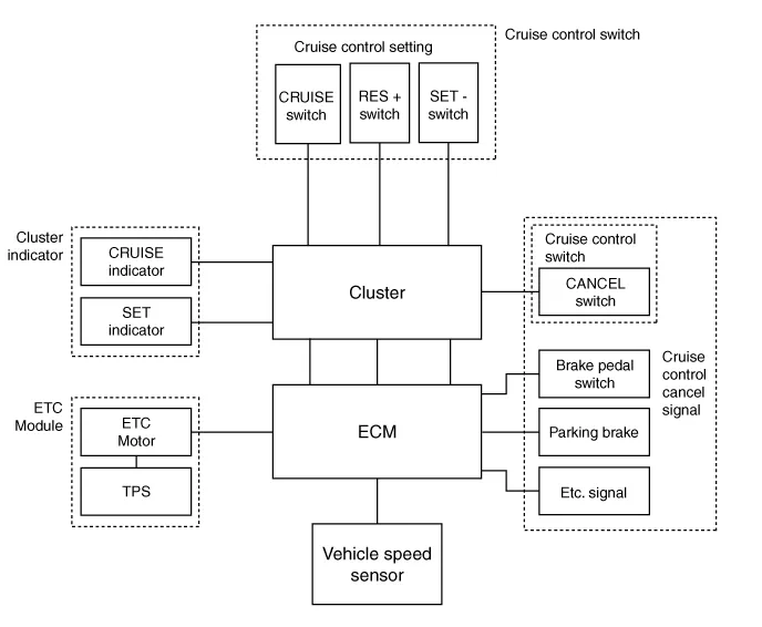
Component Parts And Function Outline
| Component part | Function | |
| Vehicle-speed sensor | Converts vehicle speed to pulse. | |
| ECM | Receives signals from sensor and control switches. | |
| Cruise control indicator | Illuminate when CRUISE main switch is ON (Built into cluster) | |
| Cruise Control switches | CRUISE switch | Switch for automatic speed control power supply. |
| RES+ switch | Controls automatic speed control functions by Resume/Accel switch (Set/Coast switch) | |
| SET- switch | ||
| Cancel switches | Cancel switch | Sends cancel signals to ECM. |
| Brake-pedal switch | ||
| Transaxle range switch (A/T) | ||
| ETC motor | Regulates the throttle valve to the set opening by ECM. | |
* ETC : Electronic Throttle Control
Cruise Control The cruise control system is engaged by the cruise "ON/OFF" main switch located on right of steering wheel column. The system has the capability to cruise, coast, accelerate and resume speed.
Other information:
Kia Cadenza YG 2016-2021 Service Manual: Temperature Control Actuator Description and Operation
D
Kia Cadenza YG 2016-2021 Service Manual: Blower Resistor Repair procedures
Inspection 1. Measure terminal - to - terminal resistance of blower resistor. 2. If measure resistance isnot within specification, the blower resistor must be replaced. Replacement 1. Disconnect the negative (-) battery terminal. 2. Remove the crash pad lower cover (A) and then disconnect the connector (B).
Categories
- Manuals Home
- Kia Cadenza Owners Manual
- Kia Cadenza Service Manual
- Transaxle Control Module (TCM) Repair procedures
- Alternator Schematic Diagrams
- Schematic Diagrams
- New on site
- Most important about car

Copyright © 2026 www.kcadenzavg.com - 0.0306