Kia Cadenza YG: Seat Electrical / Seat Heater Components and Components Location
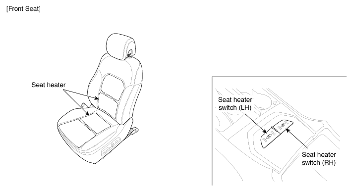
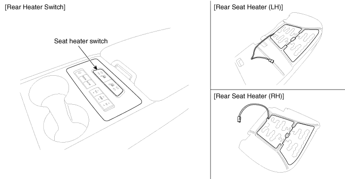
| Component Location |
Inspection With the power seat switch in each position, make sure that continuity exists between the terminals below. If continuity is not as specified, replace the power seat switch.
Circuit Diagram
Other information:
Kia Cadenza YG 2016-2021 Service Manual: Height Sensor Repair procedures
Removal Height Sensor 1. Disconnect the negative (-) battery terminal. 2. Remove the height sensor linkage (A) installed on the front axle and rear axle. [Front] [Rear] Installation Height Sensor 1. Install the height sensor assembly after connecting the connector.
Kia Cadenza YG 2016-2021 Service Manual: Compressor Repair procedures
Removal 1. If the compressor is marginally operable, run the engine at idle speed, and let the air conditioning work for a few minutes, then shut the engine off. 2. Disconnect the negative cable from the battery. 3. Recover the refrigerant with a recovery/charging station.
Categories
- Manuals Home
- Kia Cadenza Owners Manual
- Kia Cadenza Service Manual
- Body (Interior and Exterior)
- Timing Chain Repair procedures
- Components and Components Location
- New on site
- Most important about car
