Kia Cadenza YG: Intake And Exhaust System / Surge Tank Repair procedures
Kia Cadenza YG 2016-2021 Service Manual / Engine Mechanical System / Intake And Exhaust System / Surge Tank Repair procedures
| Removal and Installation |
To avoid damage, unplug the wiring connectors carefully while holding the connector portion. |

Mark all wiring and hoses to avoid misconnection. |

| 1. |
Drain the coolant.
(Refer to Cooling System – “Coolant”) |
| 2. |
Remove the air cleaner assembly.
(Refer to Intake And Exhaust system - "Air Cleaner") |
| 3. |
Disconnect the wiring connectors and harness clamps and remove the wiring protector around the surge tank.
|
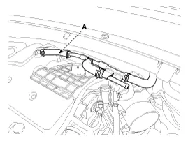
| 4. |
Disconnect the brake vacuum hose (A).
|
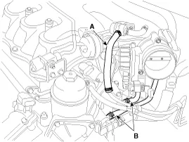
| 5. |
Disconnect the PCSV hose (A), and the throttle body water hoses (B).
|
| 6. |
Disconnect the PCV hose (A), and then remove the surge tank stay (B).
|

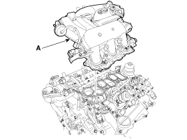
| 7. |
Remove the surge tank (A).
|
| 8. |
Install in the reverse order of removal. |
| 9. |
Fill the engine coolant after check coolant level. |
Components 1. Surge tank2. Surge tank stay
Components 1. Intake manifold
Other information:
Kia Cadenza YG 2016-2021 Service Manual: Description and Operation
System Overview RPAS (Rear Parking Assist System) is an electronic driving aid that warns the driver to be cautious while parking or in low speed environments. The sensor uses ultrasonic waves to detect objects within proximity of the vehicle.
Kia Cadenza YG 2016-2021 Service Manual: Cluster ionizer Repair procedures
Inspection 1. Press the OFF switch more then 4 times within 2 seconds while pressing the MODE switch. DisplayFail description00Normal50Cluster ionizer fault * Diagnostic procedure refer to DTC code. Replacement 1. Disconnect the negative (-) battery terminal.
Categories
- Manuals Home
- Kia Cadenza Owners Manual
- Kia Cadenza Service Manual
- Emission Control System
- Brake System
- Components and Components Location
- New on site
- Most important about car

Copyright © 2026 www.kcadenzavg.com - 0.0159