Kia Cadenza YG: Tires/Wheels / Tire Repair procedures
| Tire wear |
| 1. |
Measure the tread depth of the tires.
|
| 2. |
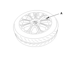
If the remaining tread depth (A) is less than the limit, replace the tire.
|


| Removal |
| 1. |
Remove the tire. |
| 2. |
Remove the foreign substance from wheel. |
| 3. |
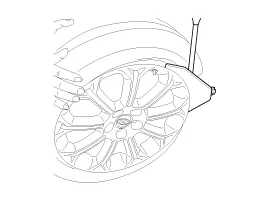
Discharge the air to the tire air inlet (A).
|
| 4. |
Install the bead brake from the tire and then remove the the tire rim by stepping slide bar, a pedal.
|
| 5. |
Carrying out the operation of the brake beads in various places until the fall tire completely from the rim. |
| 6. |
Put on the wheel turn table and then, fixed to the turntable wheel by stepping slide bar, a pedal. |
| 7. |
Install the rim of the wheel head mounting and then fixed.
|


| 8. |
Install the lever and then located to top tire between.
|
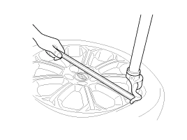
| 9. |
By stepping turntable pedal, rotated clockwise the turntable and then separate from the wheel outside the tire. |
| 10. |
Inside of the tire, it is to remove the tire from the wheel in the same way as No. 10.
|

| 11. |
Install in the reverse order of removal. |
Hub nut tightening sequence Tighten the hub nuts as follows. Tightening torque: 88.3 ~ 107.9N.m (9.0 ~ 11.0kgf.m, 65.1 ~ 79.6lb-ft) When using an impact gun, final tightening torque should be checked using a torque wrench.
Other information:
Kia Cadenza YG 2016-2021 Service Manual: Blind Spot Detection Radar Calibration Description and Operation
Description To sense the cars exactly in the next lane with the radar, the direction of the sensor and the direction of the vehicle have to align. This is BSD unit alignment. If this alignment is not performed as below illustration, the degradation of detection performance and the cause of false alarms.
Kia Cadenza YG 2016-2021 Service Manual: Troubleshooting
Troubleshooting Problem Symptoms Table Before replacing or repairing air conditioning components, first determine if the malfunction is due to the refrigerant charge, air flow or compressor. Use the table below to help you find the cause of the problem.
Categories
- Manuals Home
- Kia Cadenza Owners Manual
- Kia Cadenza Service Manual
- Timing Chain Repair procedures
- Engine Control / Fuel System
- Brake System
- New on site
- Most important about car
