Kia Cadenza YG: Automatic Transaxle Control System / Transaxle Control Module (TCM) Description and Operation
| Description |
| • |
Monitors the vehicle''s operating conditions to determine the optimal gear setting. |
| • |
Performs a gear change if the current gear setting differs from the identified optimal gear setting. |
| • |
Determines the need for Damper Clutch (D/C) activation and engages the clutch accordingly. |
| • |
Calculates the optimal line pressure level by constantly monitoring the torque level and adjusts the pressure accordingly. |
| • |
Diagnoses the automatic transaxle for faults and failures. |
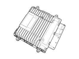
Components Location [Vehicle Components] 1. Automatic transaxle2. Transaxle Control Module (TCM)3. Shift lever4. Date Linke Connector (DLC) [Transaxle Components] 1.
1. TCM connector and terminal function 2. TCM terminal function Connector [A] PinDescriptionPinDescription1-45Inhibitor switch signal ''S2''2-46Inhibitor switch signal ''S3''3-47Inhibitor switch signal ''S4''4-48-5-49-6-50-7-51-8-52-9-53-10CAN communication line (HIGH)54Sports mode down switch11-55-12-56-13-57-14-58-15-59-16-60-17-61-18-62-19-63-20-64-21-65-22-66-23-67-24-68-25-69-26-70-27Ignition switch71-28-72-29Sports mode up switch73-30-74-31-75-32-76-33-77-34-78 35CAN communication line Low79Sports mode Select switch36-80-37-81-38-82-39-83-40-84Shift lock solenoid41-85Reverse lamp relay42-86P/N relay43-87-44Inhibitor switch signal ''S1''88- Connector [B] PinDescriptionPinDescription1Overdrive clutch control solenoid valve (VFS)52Underdrive brake control solenoid valve (VFS)3Input speed sensor signal53SS-B Solenoid valve (ON/OFF)4Output speed sensor signal54Output speed sensor power26Torque converter control solenoid valve (VFS)55Oil temperature sensor (-)2735R Clutch control solenoid valve (VFS)57Oil temperature sensor (+)28SS-A Solenoid valve (ON/OFF) 76Solenoid valve power 129Input speed sensor power77Solenoid valve power 251Line pressure control solenoid valve (VFS)7826 Brake control solenoid valve (VFS) 3.
Other information:
Kia Cadenza YG 2016-2021 Service Manual: Troubleshooting
Troubleshooting Examples of False-Alarm Occurrence from system characteristics (It’s not a problem) – Characteristics of EM Wave : EM Waves are reflected against all material and especially metal very well. Reflections of EM Waves are varies with the shape of object.
Kia Cadenza YG 2016-2021 Service Manual: Temperature Control Actuator Repair procedures
Inspection 1. Ignition "OFF" 2. Disconnect the connector of temperature control actuator. 3. Verify that the temperature control actuator operates to the hot position when connecting 12V to the terminal 3 and grounding terminal 7. Verify that the temperature control actuator operates to the cool position when connecting in the rev
Categories
- Manuals Home
- Kia Cadenza Owners Manual
- Kia Cadenza Service Manual
- Restraint
- Timing Chain Repair procedures
- Schematic Diagrams
- New on site
- Most important about car
