Kia Cadenza YG: Automatic Transaxle Control System / Components and Components Location
| Components Location |
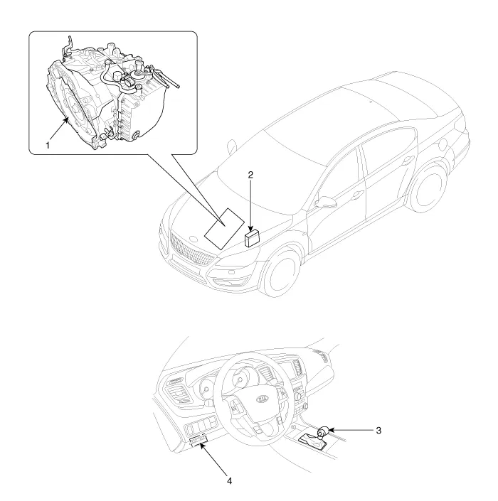
| 1. Automatic transaxle 2. Transaxle Control Module (TCM) | 3. Shift lever 4. Date Linke Connector (DLC) |
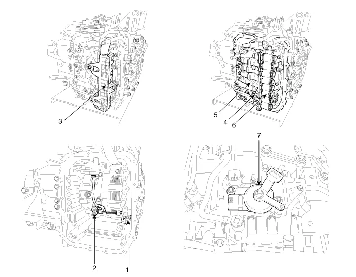
| 1. Input speed sensor 2. Output speed sensor 3. Solenoid valve connect 4. Oil Temperature Sensor (OTS) | 5. Valve body assembly 6. Solenoid valve 7. Inhibitor switch |
Circuit Diagram
Description Transaxle Control Module (TCM) is the automatic transaxle''s brain. The module receives and processes signals from various sensors and implements a wide range of transaxle controls to ensure optimal driving conditions for the driver.
Other information:
Kia Cadenza YG 2016-2021 Service Manual: Repair procedures
Inspection Initialization and diagnosis sequence by using diagnostic equipment Below content summarize the procedure for A/S using Diagnostic equipment Download Parameter 1. Select "AFLS" menu after selecting a vehicle. 2. Select "Parameter download" menu for define a characteristc of vehicle.
Kia Cadenza YG 2016-2021 Service Manual: Surround View Monitoring Switch Repair procedures
Removal 1. Disconnect the negative (-) battery terminal. 2. Remove the floor console upper cover. (Refer to Body - "Floor Console Assembly") 3. Disconnect the console upper cover connector (A). 4. Remove the cup holder assembly (A) after loosening the mounting screws.
Categories
- Manuals Home
- Kia Cadenza Owners Manual
- Kia Cadenza Service Manual
- Components and Components Location
- Schematic Diagrams
- General Information
- New on site
- Most important about car
