Kia Cadenza YG: Automatic Transaxle Control System / Transaxle Oil Temperature Sensor Repair procedures
Kia Cadenza YG 2016-2021 Service Manual / Automatic Transaxle System / Automatic Transaxle Control System / Transaxle Oil Temperature Sensor Repair procedures
| Inspection |
| 1. |
Turn ignition switch OFF. |
| 2. |
Remove the battery and battery tray.
(Refer to Engine Electrical System - "Battery") |
| 3. |
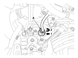
Disconnect the solenoid valve connector (A).
|
| 4. |
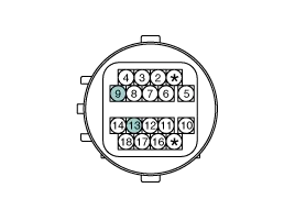
Measure the resistance between + terminal (9) and - terminal (13).
|
| 5. |
Check that the resistance is within the specification.
|
| Removal |
The oil temperature sensor is integrated with the solenoid
valve main connector and can not be disassembled. The oil temperature
sensor should be replaced with the solenoid valve main connector. |

| 1. |
Move the shift lever to "N" range. |
| 2. |
Remove the valve body assembly.
(Refer to Hydraulic System - "Valve Body") |
| 3. |
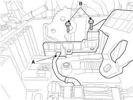
Disconnect the input & output speed sensor connector (A). |
| 4. |
Loosen the solenoid valve harness bolts (B).
|
| 5. |
Disconnect the solenoid valve connector (A).
|
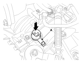
| 6. |
Remove the clip (A) and then remove the connector by pressing it downward.
|
| Installation |
| 1. |
Install in the reverse order of removal. |
|

Circuit Diagram
Description Input speed sensor is a vital unit that measures the rate of rotation of the input shaft inside the transaxle and delivers the readings to the Transaxle Control Module(TCM).
Other information:
Kia Cadenza YG 2016-2021 Service Manual: Pantoscopic Camera Repair procedures
Removal Front Pantoscopic Camera 1. Disconnect the negative (-) battery terminal. 2. Remove the front bumper cover. (Refer to Body - "Front Bumper Cover") 3. Remove the pantocscpic camera (B) after loosening the mounting screws and connector (A).
Kia Cadenza YG 2016-2021 Service Manual: Heater Unit Components and Components Location
Component Location Components 1. Heater Case (LH)2. Separator3. Evaporator Core4. Shower Duct (LH)5. Heater Core Cover6. Heater Core7. Mode Actuator8. Mode Cam9. Temp Actuator (Drive)10. Vent Door Arm11. Floor Door Arm 1. Heater Case (RH)2.
Categories
- Manuals Home
- Kia Cadenza Owners Manual
- Kia Cadenza Service Manual
- Engine Electrical System
- Components and Components Location
- Body (Interior and Exterior)
- New on site
- Most important about car

Copyright © 2026 www.kcadenzavg.com - 0.0254