Kia Cadenza YG: Engine Control System / Variable Intake Solenoid (VIS) Valve Repair procedures
| Inspection |
| 1. |
Turn the ignition switch OFF. |
| 2. |
Disconnect the VIS valve connector. |
| 3. |
Measure resistance between the VIS valve terminals 1 and 2. |
| 4. |
Check that the resistance is within the specification.
|
| Removal |
| 1. |
Turn the ignition switch OFF and disconnect the battery negative (-) cable. |
| 2. |
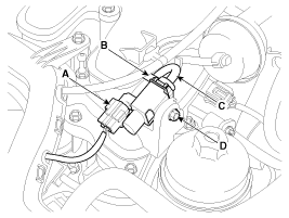
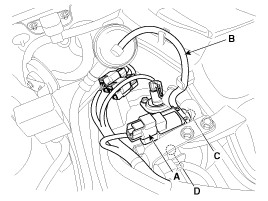
Disconnect the variable intake solenoid valve connector (A). |
| 3. |
Disconnect the vacuum hoses (B, C) from the valve. |
| 4. |
Remove the installation nut (D), and then remove the valve.
[Vave 1 (Intake manifold)]
[Vave 2 (Surge tank)]
|
| Installation |
|

|
| 1. |
Install in the reverse order of removal.
|
Circuit Diagram
Description Fuel Pressure Control Valve is installed on the high pressure fuel pump and controls fuel flow flowing into the injectors in accordance with the ECM signal calculated based on various engine condition.
Other information:
Kia Cadenza YG 2016-2021 Service Manual: Repair procedures
Removal 1. Remove the trunk trim in the trunk after removing the screws and clips. (Refer to Body - "Trunk") 2. Remove the camera holder (A) as shown arrow direction, and then remove the back view camera (B). Installation 1. Install the back view camera and camera holder.
Kia Cadenza YG 2016-2021 Service Manual: Troubleshooting
Troubleshooting Problem Symptoms Table Before replacing or repairing air conditioning components, first determine if the malfunction is due to the refrigerant charge, air flow or compressor. Use the table below to help you find the cause of the problem.
Categories
- Manuals Home
- Kia Cadenza Owners Manual
- Kia Cadenza Service Manual
- Transaxle Control Module (TCM) Repair procedures
- Brake System
- Steering System
- New on site
- Most important about car
