Kia Cadenza YG: ESC(Electronic Stability Control) System / Yaw-rate and G Sensor Description and Operation
Kia Cadenza YG 2016-2021 Service Manual / Brake System / ESC(Electronic Stability Control) System / Yaw-rate and G Sensor Description and Operation
| Description |
When the vehicle is turning with respect to a vertical axis
the yaw rate sensor detects the yaw rate electroniclly by the vibration
change of plate fork inside the yaw rate sensor.
If yaw velocity reaches the specific velocity after it detects the vehicle''yawing, the ESP control is reactivated.
The later G sensor senses vehicle''s lateral G. A small
element inside the sensor is attached to a deflectable leverarm by later
G.
Direction and magnitude of lateral G loaded to vehicle can be known with electrostatic capacity changing according to lateral G.
Specifications
| Description | Specification | Remarks | |
| Operating voltage | 10 ~ 16V | ||
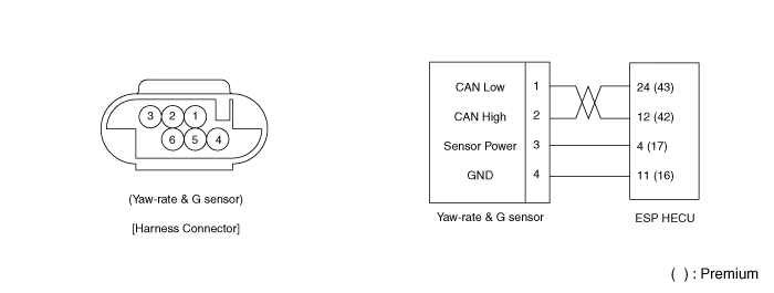
| Output signal | CAN Interface | ||
| Operating temperature | -40 ~ 85°C (-40 ~ 185°F) | ||
| Yaw-rate sensor | Measurement range | -75 ~ 75°/sec | |
| Frequency response | 15 ~ 45Hz | ||
| Lateral G sensor | Measurement range | -14.715 ~ 14.715m/s² | |
| Frequency response | 50Hz ± 60% (±3dB) | ||
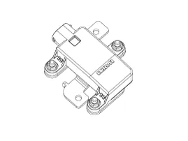
External Diagram
Removal 1. Remove the rear wheel and tire. Tightening torque: 88.3 ~ 107.9 N.m (9.0 ~ 11.0 kgf.m, 65.1 ~ 79.6 lb-ft) 2. Remove the rear wheel speed sensor mounting bolt (A).
Removal 1. Turn ignition switch OFF and disconnect the negative (-) battery cable. 2. Remove the floor console. (Refer to the Body - "Console") 3.
Other information:
Kia Cadenza YG 2016-2021 Service Manual: Specifications
S
Kia Cadenza YG 2016-2021 Service Manual: Height Sensor Repair procedures
Removal Height Sensor 1. Disconnect the negative (-) battery terminal. 2. Remove the height sensor linkage (A) installed on the front axle and rear axle. [Front] [Rear] Installation Height Sensor 1. Install the height sensor assembly after connecting the connector.
Categories
- Manuals Home
- Kia Cadenza Owners Manual
- Kia Cadenza Service Manual
- Alternator Schematic Diagrams
- Components and Components Location
- Engine Control / Fuel System
- New on site
- Most important about car

Copyright © 2026 www.kcadenzavg.com - 0.0219