Kia Cadenza YG: Engine Control System / Knock Sensor (KS) Schematic Diagrams
| Circuit Diagram |
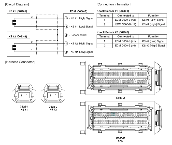
Specification ItemSpecificationCapacitance (pF)950 ~ 1,350Resistance (MΩ)4.87
Removal [Knock Sensor #1 (Bank 1)] 1. Turn the ignition switch OFF and disconnect the battery negative (-) cable. 2. Disconnect the knock sensor connector (A).
Other information:
Kia Cadenza YG 2016-2021 Service Manual: Adaptive Front Lighting System Description and Operation
Description AFLS Unit(ECU) AFLS located in Cockpit Module is provided information of vehicle (steering wheel signal,vehicle speed, inclination of vehicle). Based on provided information , it calculates algorithm and adjust Low beam of H/Lamp. It transmits driving information by using LIN protocol, it is operated in Fail-safe reaction mode
Kia Cadenza YG 2016-2021 Service Manual: General Safety Information and Caution
Instructions When Handling Refrigerant 1. R-134a liquid refrigerant is highly volatile. A drop on the skin of your hand could result in localized frostbite. When handling the refrigerant, be sure to wear gloves. 2. It is standard practice to wear goggles or glasses to protect your eyes, and gloves to protect your hands.
Categories
- Manuals Home
- Kia Cadenza Owners Manual
- Kia Cadenza Service Manual
- Body (Interior and Exterior)
- Engine Electrical System
- Timing Chain Repair procedures
- New on site
- Most important about car
