Kia Cadenza YG: Lubrication System / Oil Pressure Switch Repair procedures
Kia Cadenza YG 2016-2021 Service Manual / Engine Mechanical System / Lubrication System / Oil Pressure Switch Repair procedures
| Removal and Installaion |
| 1. |
Remove the intake manifold.
(Refer to Intake And Exhaust System - "Intake Manifold") |
| 2. |
Remove the delivery pipe and injector.
(Refer to Engine Control / Fuel System - "Delivery Pipe") |
| 3. |
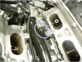
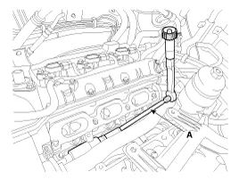
Remove the oil pressure switch (A) after disconnecting the connector.
|

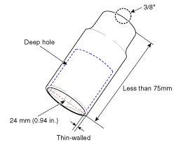
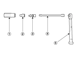
 24mm deep socket
 1/2" to 3/8" drive socket adapter (only if using 1/2" drive deep socket)
 3/8" universal joint
 3/8" extension bar
 Socket wrench
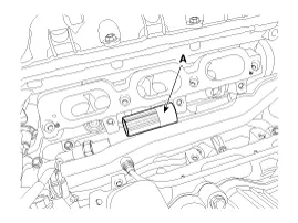
| 4. |
Install in the reverse order of removal.
|
| Inspection |
| 1. |
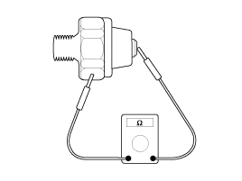
Check the continuity between the terminal and the body with an ohmmeter.
If there is no continuity, replace the oil pressure switch.
|
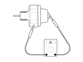
| 2. |
Check the continuity between the terminal and the body when
the fine wire is pushed. If there is continuity even when the fine wire
is pushed, replace the switch.
|
| 3. |
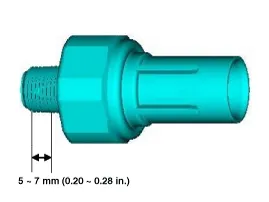
If there is no continuity when a 50 kpa (7psi) is applied
through the oil hole the switch is operaing properly. Check for air
leakage. If air leaks, the diaphragm is broken. Replace it. |
Components 1. Oil cover2. Oil cover gasket3. Oil pressure switch
Components 1. Oil level gauge2. Oil level gauge pipe3. O-ring
Other information:
Kia Cadenza YG 2016-2021 Service Manual: General Safety Information and Caution
Instructions When Handling Refrigerant 1. R-134a liquid refrigerant is highly volatile. A drop on the skin of your hand could result in localized frostbite. When handling the refrigerant, be sure to wear gloves. 2. It is standard practice to wear goggles or glasses to protect your eyes, and gloves to protect your hands.
Kia Cadenza YG 2016-2021 Service Manual: Cluster ionizer Repair procedures
Inspection 1. Press the OFF switch more then 4 times within 2 seconds while pressing the MODE switch. DisplayFail description00Normal50Cluster ionizer fault * Diagnostic procedure refer to DTC code. Replacement 1. Disconnect the negative (-) battery terminal.
Categories
- Manuals Home
- Kia Cadenza Owners Manual
- Kia Cadenza Service Manual
- Engine Electrical System
- Body Electrical System
- Fuel Delivery System
- New on site
- Most important about car

Copyright © 2026 www.kcadenzavg.com - 0.0221