Kia Cadenza YG: Hydraulic System / Oil Pump Description and Operation
| Description |
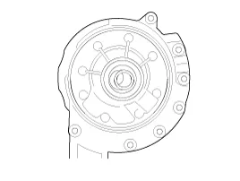
Components Location 1. Automatic transaxle2. Valve body assembly3. Oil pump assembly
Components 1. Reaction shaft support assembly2. Oil pump housing3. Driven gear4. Drive gear5. Oil seal6. Bush-Housing7. Reaction shaft8. Bush- Reaction shaft9.
Other information:
Kia Cadenza YG 2016-2021 Service Manual: Repair procedures
Teaching Procedures 1. Key Teaching Procedure Key teaching must be done after replacing a defective PCM(ECM) or when providing additional keys to the vehicle owner. The procedure starts with an PCM(ECM) request for vehicle specific data (PIN code: 6digits) from the tester.
Kia Cadenza YG 2016-2021 Service Manual: Description and Operation
Description System Operation Typically, lane departure warning is activated at a speed over 70 KPH, but suppressed in case of unintentional lane departure when driver do not operate turn signal. System Operation Conditions 1. User Conditions (1) When unintended lane departure is occured, warnings are generated.
Categories
- Manuals Home
- Kia Cadenza Owners Manual
- Kia Cadenza Service Manual
- Battery Troubleshooting
- Components and Components Location
- Emission Control System
- New on site
- Most important about car
