Kia Cadenza YG: Rear Glass Defogger / Rear Glass Defogger Switch Repair procedures
| Inspection |
| 1. |
The rear glass defogger switch inputs can be checked using the GDS. |
| 2. |
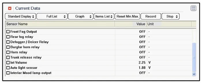
To check the input value of rear glass defogger switch, select option "IPM". |
| 3. |
To consult the present input/output value of IPM, "Current
DATA". It provides information of IPM input/output conditions of rear
defogger relay.
|
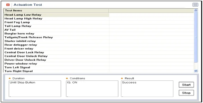
| 4. |
To check the input value of rear glass defogger switch in force mode, select option "Actuation Test".
|
| Removal |
| 1. |
Disconnect the negative (-) battery terminal. |
| 2. |
Remove the center fascia panel.
(Refer to Body - "Crash Pad") |
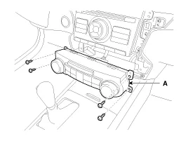
| 3. |
Remove the heater control unit (A) after removing screws (4EA).
|
| Installation |
| 1. |
Install the heater control unit. |
| 2. |
Install the center fascia panel. |
Inspection Wrap tin foil around the end of the voltmeter test lead to prevent damaging the heater line. Apply finger pressure on the tin foil, moving the tin foil along the grid line to check for open circuits.
Other information:
Kia Cadenza YG 2016-2021 Service Manual: Repair procedures
Diagnosis With GDS 1. BSD system defects can be quickly diagnosed with the GDS. GDS operates actuator quickly to monitor, input/output value and self diagnosis. 2. Connect the cable of GDS to the data link connector in driver side crash pad lower panel, turn the power on GDS.
Kia Cadenza YG 2016-2021 Service Manual: Blind Spot Detection Variant Coding Description and Operation
Description The used radar frequency of BSD is two, "North America region" and "Except North America region". If it replaces BSD unit, BSD unit has to perform the procedure of variant coding. BSD Variant Coding 1. Select the "BSD Variant Coding" procedure in BSD system.
Categories
- Manuals Home
- Kia Cadenza Owners Manual
- Kia Cadenza Service Manual
- Alternator Schematic Diagrams
- Engine Electrical System
- Transaxle Control Module (TCM) Repair procedures
- New on site
- Most important about car
