
Kia Cadenza YG: Seat Electrical / Seat Heater Switch Repair procedures
Kia Cadenza YG 2016-2021 Service Manual / Body Electrical System / Seat Electrical / Seat Heater Switch Repair procedures
| Inspection |
Front Seat Heater Switch
| 1. |
Disconnect the negative (-) battery terminal. |
| 2. |
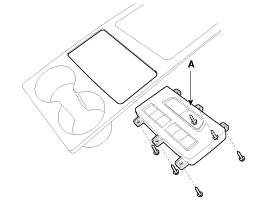
Remove the floor console upper cover (A).
(Refer to Body - "Console") |
| 3. |
Remove the seat heater switch connector (A) from the floor console upper cover.
|
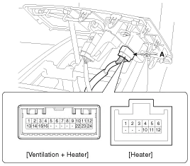
| 4. |
Operate each seat heater switch and check that continuity exists between the terminals.
If there is no continuity, replace the seat heater switch
[Ventilation + Heater]
[Ventilation + Heater]
[Heater]
|
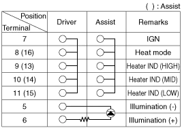
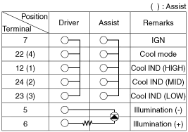
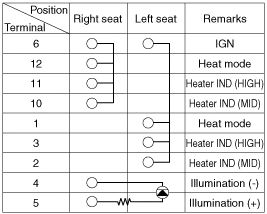
Rear Seat Heater Switch
| 1. |
Disconnect the negative (-) battery terminal. |
| 2. |
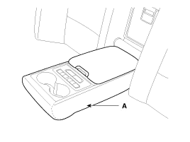
Open the rear seat arm rest (A).
|
| 3. |
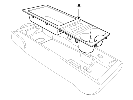
Remove the rear seat arm rest upper cover (A).
|
| 4. |
Disconnect the connector (A).
|

| 5. |
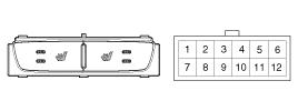
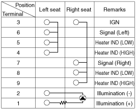
Turn rear seat heater switch ON and check that continuity exists between the terminals.
|
| 6. |
If there is no continuity, replace the seat heater switch (A).
|
Circuit Diagram
Components (1) 1. Ventilation blower2. Ventilation ECU3. Ventilation seat switch Components (2)
Other information:
Kia Cadenza YG 2016-2021 Service Manual: Refrigerant line Repair procedures
Replacement 1. Discharge refrigerant from refrigeration system. 2. Replace faulty tube or hose. Cap the open fittings immediately to keep moisture or dirt out of the system. 3. Tighten joint of bolt or nut to specified torque.
Kia Cadenza YG 2016-2021 Service Manual: Power Mosfet Repair procedures
Inspection 1. Ignition "ON" 2. Manually operate the control switch and measure the voltage of blower motor. 3. Select the control switch to raise voltage until high speed. Specification FanMotor VoltageManualFirst speed3.8 ±0.5VSecond speed5.
Categories
- Manuals Home
- Kia Cadenza Owners Manual
- Kia Cadenza Service Manual
- Engine Electrical System
- General Information
- Schematic Diagrams
- New on site
- Most important about car

Copyright © 2026 www.kcadenzavg.com - 0.025