Kia Cadenza YG: Smart Cruise Control System / Smart Cruise Control Switch Schematic Diagrams
| Circuit Diagram |
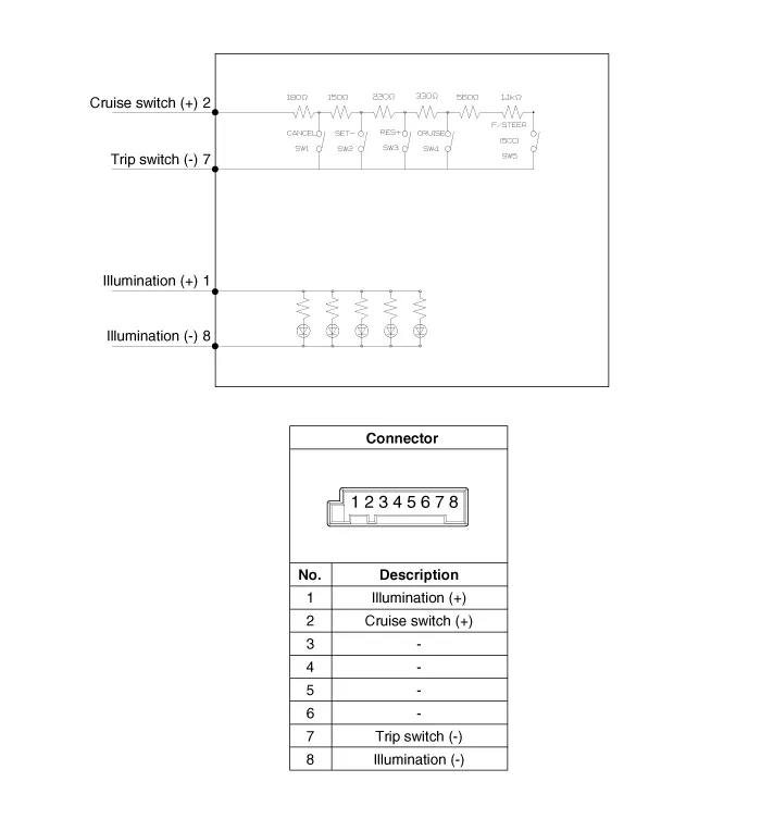
Components 1. SET - switch2. RES + switch3. SCC switch4. CANCEL switch5. CRUISE switch
Inspection [Measuring Resistance] 1. Disconnect the cruise control switch connector from the control switch. 2. Measure resistance between terminals on the control switch when each function switch is ON (switch is depressed).
Other information:
Kia Cadenza YG 2016-2021 Service Manual: Blower Motor Repair procedures
Inspection 1. Connect the battery voltage and check the blower motor rotation. 2. If the blower motor voltage is not operated well, substitute with a known-good blower motor and check for proper operation. 3. If the problem is corrected, replace the blower motor.
Kia Cadenza YG 2016-2021 Service Manual: Heater & A/C Control Unit (DATC) Repair procedures
Inspection Self diagnosis 1. Self-diagnosis process 2. How to read self-diagnostic code. After the display panel flickers three times every 0.5 second, the corresponding fault code flickers on the setup temperature display panel every 0.
Categories
- Manuals Home
- Kia Cadenza Owners Manual
- Kia Cadenza Service Manual
- Transaxle Control Module (TCM) Repair procedures
- Engine Mechanical System
- Automatic Transaxle System
- New on site
- Most important about car
