Kia Cadenza YG: Electric Power Steering / Steering Gear box Components and Components Location
| Components |
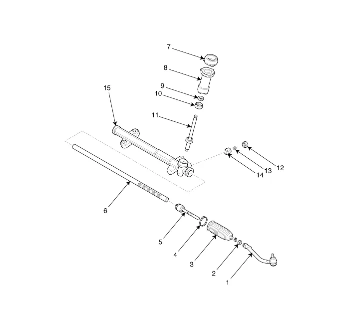
| 1. Tie-rod end 2. Lock nut 3. Bellows 4. Bellows clip 5. Tie rod | 6. Rack bar 7. Dust packing 8. Dust cap 9. Oil seal 10. Pinion plug | 11. Pinion assembly 12. Yoke plug 13. Yoke spring 14. Support yoke assembly 15. Rack housing |
Replacement 1. Disconnect the battery negative cable from the battery and then wait for at least 30 seconds. 2. Turn the steering wheel so that the front wheels can face straight ahead.
Replacement 1. Remove the front wheel & tire (A). Tightening torque : 88.3 ~ 107.9N.m (9.0 ~ 11.0kgf.m, 65.1 ~ 79.6lb-ft) • Be careful not to damage to the hub bolts when removing the front wheel & tire.
Other information:
Kia Cadenza YG 2016-2021 Service Manual: A/C Pressure Transducer Repair procedures
Inspection 1. Measure the pressure of high pressure line by measuring voltage output between NO.1 and NO.2 terminals. 2. Inspect the voltage value whether it is sufficient to be regular value or not. Voltage = 0.00878835 * Pressure + 0.37081095 [PSIA] 3.
Kia Cadenza YG 2016-2021 Service Manual: Auto defoging sensor Repair procedures
Inspection 1. Press the OFF switch more then 4 times within 2 seconds while pressing the MODE switch. DisplayFail description00Normal23Auto defog sensor OPEN24Auto defog sensor SHORT43Defog door potentiometer OPEN/SHORT44Defog door potentiometer * Diagnostic procedure refer to DTC code.
Categories
- Manuals Home
- Kia Cadenza Owners Manual
- Kia Cadenza Service Manual
- Engine Control / Fuel System
- Components and Components Location
- Alternator Schematic Diagrams
- New on site
- Most important about car
