Kia Cadenza YG: Intake And Exhaust System / Surge Tank Components and Components Location
Kia Cadenza YG 2016-2021 Service Manual / Engine Mechanical System / Intake And Exhaust System / Surge Tank Components and Components Location
| Components |
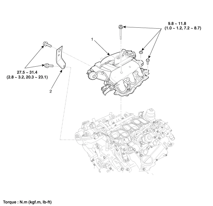
| 1. Surge tank 2. Surge tank stay |
Removal and Installation 1. Remove the battery. (Refer to Engine Electrical System - "Battery") 2. Remove the engine cover. 3. Remove the air duct (A).
Removal and Installation To avoid damage, unplug the wiring connectors carefully while holding the connector portion. Mark all wiring and hoses to avoid misconnection.
Other information:
Kia Cadenza YG 2016-2021 Service Manual: Compressor Repair procedures
Removal 1. If the compressor is marginally operable, run the engine at idle speed, and let the air conditioning work for a few minutes, then shut the engine off. 2. Disconnect the negative cable from the battery. 3. Recover the refrigerant with a recovery/charging station.
Kia Cadenza YG 2016-2021 Service Manual: Temperature Control Actuator Description and Operation
D
Categories
- Manuals Home
- Kia Cadenza Owners Manual
- Kia Cadenza Service Manual
- General Information
- Components and Components Location
- Emission Control System
- New on site
- Most important about car

Copyright © 2026 www.kcadenzavg.com - 0.0248