Kia Cadenza YG: MTS System / Telemetics Unit (TMU) Repair procedures
| Removal |
|

| 1. |
Disconnect the negative (-) battery terminal. |
| 2. |
Remove the AVN monitor.
(Refer to "AVN System" - "AVN Head Unit") |
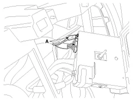
| 3. |
Remove the TMU unit (A) after loosening the mounting screws.
|
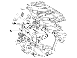
| 4. |
Disconnect the connectors (A) from the TMU unit.
|
| Installation |
| 1. |
Install the TMU unit after connecting the connector. |
| 2. |
Install the AVN monitor. |
| 3. |
Connect the negative (-) battery terminal. |
| Inspection |
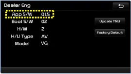
| 1. |
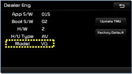
After replacing the TMU unit, access Dealer Engineering Mode in head unit.
(Refer to MTS system - "TMU Dealer Engineering Mode") |
| 2. |
Check the TMU version ("App S/W") from the head unit screen.
|
| 3. |
Check the H/U Type from the head unit screen.
|
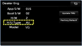
| 4. |
Check the Model from the head unit screen.
|
Component Connector Pin Specification No.Pin NameTypeFromToDescription (Wiring Spec.)1GNDDC GroundTMUBatteryConnected to battery ground2GNDDC GroundTMUBatteryConnected to battery ground3-----4-----5-----6-----7-----8-----9-----10-----11-----12HS CAN (-)Data I/OBUSBUSHigh Speed CAN bus low13HS CAN (+)Data I/OBUSBUSHigh Speed CAN bus high14-----15-----16-----17-----18V battery 1DC InputBatteryTMUDC level input from battery Supply power to TMU19Ignition 1Data InputJunction BoxTMUVehicle Key mode status20ACCData InputJunction BoxTMUVehicle Key mode status21AirbagData InputACUTMUAirbag status data from ACU22-----23-----24-----25-----26-----27-----28-----29-----30-----31MM CAN (-)Data I/OBUSBUSLow Speed CAN bus low32MM CAN (+)Data I/OBUSBUSLow Speed CAN bus high
Other information:
Kia Cadenza YG 2016-2021 Service Manual: Description and Operation
System Overview RPAS (Rear Parking Assist System) is an electronic driving aid that warns the driver to be cautious while parking or in low speed environments. The sensor uses ultrasonic waves to detect objects within proximity of the vehicle.
Kia Cadenza YG 2016-2021 Service Manual: Blind Spot Detection Unit Repair procedures
Removal 1. Disconnect the negative (-) battery terminal. 2. Remove the rear bumper. (Refer to Body - "Rear Bumper") 3. Remove the BSD unit (A) after loosening the mounting screws. Take care not to separate the bracket from rear bumper when removing the BSD sensor.
Categories
- Manuals Home
- Kia Cadenza Owners Manual
- Kia Cadenza Service Manual
- Body Electrical System
- Timing Chain Repair procedures
- Steering System
- New on site
- Most important about car
