
Kia Cadenza YG: Heater / Temperature Control Actuator Repair procedures
Kia Cadenza YG 2016-2021 Service Manual / Heating,Ventilation, Air Conditioning / Heater / Temperature Control Actuator Repair procedures
| Inspection |
| 1. |
Ignition "OFF" |
| 2. |
Disconnect the connector of temperature control actuator. |
| 3. |
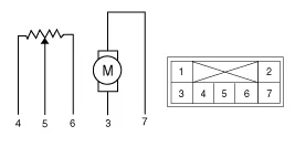
Verify that the temperature control actuator operates to the
hot position when connecting 12V to the terminal 3 and grounding
terminal 7.
Verify that the temperature control actuator operates to the cool position when connecting in the reverse.
[Drive]
|
| 4. |
Check the voltage between terminals 5 and 6(Drive).
Specification
[Passenger]
|
| 5. |
Check the voltage between terminals 5 and 6(Passenger).
Specification
It will feedback current position of actuator to controls. |
| 6. |
If the measured voltage is not specification, substitute with
a known-good temperature control actuator and check for proper
operation. |
| 7. |
If the problem is corrected, replace the temperature control actuator. |
| Replacement |
| 1. |
Disconnect the negative (-) battery terminal. |
| 2. |
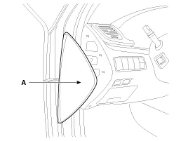
Remove the crash pad left side cover (A).
|
| 3. |
Remove the console side cover [LH].
(Refer to BD group - "Console") |
| 4. |
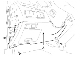
Disconnect the connector(A) and then remove the crash pad lower cover.
|
| 5. |
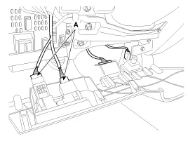
Disconnect the diagnosis connectors (A) and then remove the crash pad lower cover.
|
| 6. |
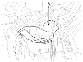
Remove the shower duct (A).
|
| 7. |
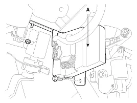
Remove the BCM (A) by loosening the mounting bolt and nut.
|
| 8. |
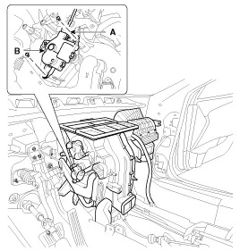
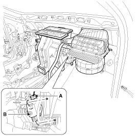
Disconnect the temperature control actuator connector (A) |
| 9. |
Loosen the mounting screw and then remove the temperature control actuator (B).
[Drive]
|
| 10. |
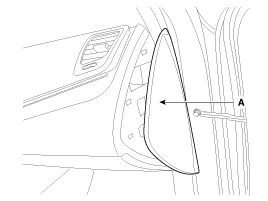
Remove the side cover(A).
|
| 11. |
Remove the console side cover [RH] (A).
|
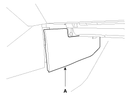
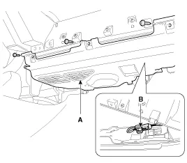
| 12. |
Remove the crash pad lower cover (A) and then disconnect the connector (B).
|
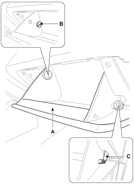
| 13. |
Disconnect the damper (B) from the glove box (A) and then remove the glove box lift (C).
|
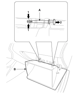
| 14. |
Disconnect the pin (A), then remove the glove box (B).
|
| 15. |
Remove the glove box housing (A) by loosening the mounting screws.
|
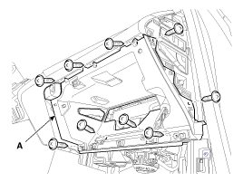
| 16. |
Disconnect the trunk lock switch connector (A) and glove box lamp connector (B).
|
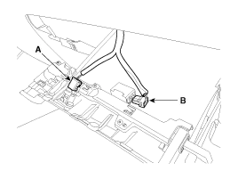
| 17. |
Disconnect the glove box switch connector (A).
|
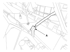
| 18. |
Remove the shower duct (A).
|
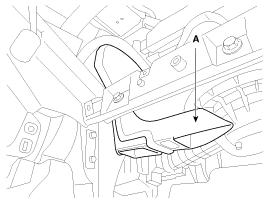
| 19. |
Disconnect the temperature control actuator connector (A) |
| 20. |
Loosen the mounting screw and then remove the temperature control actuator (B).
[Passenger]
|
| 21. |
Installation is the reverse order of removal. |
Description 1. Heater unit includes mode control actuator and temperature control actuator. 2. Temperature control actuator is located at the heater unit.
Component Location
Other information:
Kia Cadenza YG 2016-2021 Service Manual: Components and Components Location
C
Kia Cadenza YG 2016-2021 Service Manual: Repair procedures
Diagnosis With GDS 1. BSD system defects can be quickly diagnosed with the GDS. GDS operates actuator quickly to monitor, input/output value and self diagnosis. 2. Connect the cable of GDS to the data link connector in driver side crash pad lower panel, turn the power on GDS.
Categories
- Manuals Home
- Kia Cadenza Owners Manual
- Kia Cadenza Service Manual
- Automatic Transaxle System
- Body Control Module (BCM) Description and Operation
- Schematic Diagrams
- New on site
- Most important about car

Copyright © 2026 www.kcadenzavg.com - 0.0238