
Kia Cadenza YG: Automatic Transaxle Control System / Transaxle Oil Temperature Sensor Repair procedures
Kia Cadenza YG 2016-2021 Service Manual / Automatic Transaxle System / Automatic Transaxle Control System / Transaxle Oil Temperature Sensor Repair procedures
| Inspection |
| 1. |
Turn ignition switch OFF. |
| 2. |
Remove the battery and battery tray.
(Refer to Engine Electrical System - "Battery") |
| 3. |
Disconnect the solenoid valve connector (A).
|
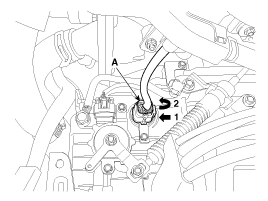
| 4. |
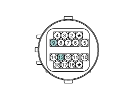
Measure the resistance between + terminal (9) and - terminal (13).
|
| 5. |
Check that the resistance is within the specification.
|
| Removal |
The oil temperature sensor is integrated with the solenoid
valve main connector and can not be disassembled. The oil temperature
sensor should be replaced with the solenoid valve main connector. |

| 1. |
Move the shift lever to "N" range. |
| 2. |
Remove the valve body assembly.
(Refer to Hydraulic System - "Valve Body") |
| 3. |
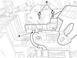
Disconnect the input & output speed sensor connector (A). |
| 4. |
Loosen the solenoid valve harness bolts (B).
|
| 5. |
Disconnect the solenoid valve connector (A).
|
| 6. |
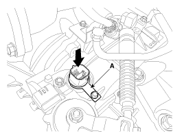
Remove the clip (A) and then remove the connector by pressing it downward.
|
| Installation |
| 1. |
Install in the reverse order of removal. |
|

Circuit Diagram
Description Input speed sensor is a vital unit that measures the rate of rotation of the input shaft inside the transaxle and delivers the readings to the Transaxle Control Module(TCM).
Other information:
Kia Cadenza YG 2016-2021 Service Manual: Specifications
Specification Air Conditioner ItemSpecificationCompressorType6VSX16Oil type & CapacityPAG OIL 100±10Pulley type6PK-TYPEDisplacement160cc/revCondenserHeat rejection14,400 ±5% kcal/hrA/C Pressure transducerThe method to measure the pressureVoltage= 0.
Kia Cadenza YG 2016-2021 Service Manual: Power Mosfet Repair procedures
Inspection 1. Ignition "ON" 2. Manually operate the control switch and measure the voltage of blower motor. 3. Select the control switch to raise voltage until high speed. Specification FanMotor VoltageManualFirst speed3.8 ±0.5VSecond speed5.
Categories
- Manuals Home
- Kia Cadenza Owners Manual
- Kia Cadenza Service Manual
- Suspension System
- General Information
- Engine Electrical System
- New on site
- Most important about car

Copyright © 2026 www.kcadenzavg.com - 0.0263