Kia Cadenza YG: Interior / Console Repair procedures
| Replacement |
|

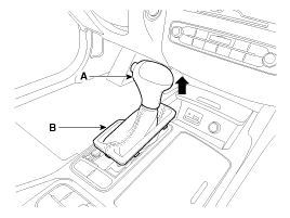
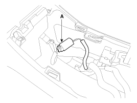
| 1. |
Using a screwdriver or remover, remove the gear boots (B). |
| 2. |
To remove the gear knob (A) and gear boots (B) pull both of it up.
|
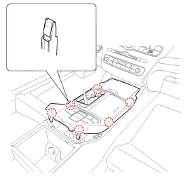
| 3. |
Using a screwdriver or remover, remove the floor console upper cover (A).
|
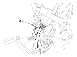
| 4. |
Disconnect the connectors (A) from the floor console upper cover .
[Rear]
[Front]
|
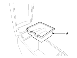
| 5. |
Remove the console armrest tray (A).
|
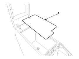
| 6. |
Remove the console tray met (A).
|
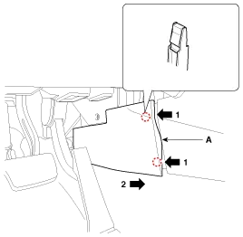
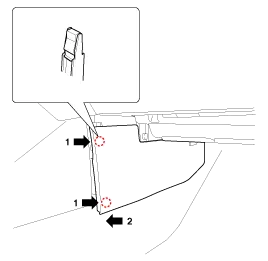
| 7. |
Using a screwdriver or remover, remove the console side cover (A).
[LH]
[RH]
|
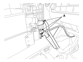
| 8. |
Disconnect the rear power outlet connector (A).
|
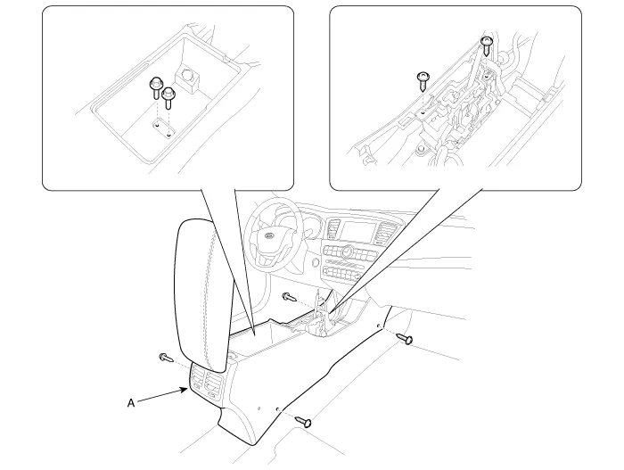
| 9. |
After loosening the mounting screws and bolts, then remove the floor console assembly (A).
|
| 10. |
Installation is the reverse of removal.
|
|
| 1. |
Remove the floor console assembly. |
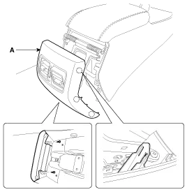
| 2. |
After loosening the mounting screws, then remove the rear console cover (A).
|
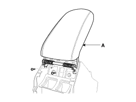
| 3. |
After loosening the mounting screws, then remove the console armrest (A).
|
| 4. |
Installation is the reverse of removal.
|
Components 1. Gear knob & boots 2. Floor console upper cover3. Floor console upper cover tray4. Console side cover [LH]5. Console side cover [RH]6.
Components 1. Main crash pad assembly2. Crash pad side cover3. Side airvent duct4. Crash pad garnish (LH)5. Cluster fascia panel6. Shroud upper panel7.
Other information:
Kia Cadenza YG 2016-2021 Service Manual: Photo Sensor Description and Operation
Description 1. The photo sensor is located at the center of defrost nozzle. 2. The photo sensor contains a photovoltaic (sensitive to sunlight) diode. The solar radiation received by its light receiving portion, generates an electromotive force in proportion to the amount of radiation received which is transferred to the automatic tem
Kia Cadenza YG 2016-2021 Service Manual: Heater Unit Repair procedures
Replacement 1. Disconnect the negative (-) battery terminal. 2. Recover the refrigerant with a recovery/ recycling/ charging station. 3. When the engine is cool, drain the engine coolant from the radiator. 4. Remove the expansion valve cover (A).
Categories
- Manuals Home
- Kia Cadenza Owners Manual
- Kia Cadenza Service Manual
- Alternator Schematic Diagrams
- Automatic Transaxle System
- Body (Interior and Exterior)
- New on site
- Most important about car
