Kia Cadenza YG: Engine Control System / Engine Control Module (ECM) Repair procedures
| Removal |
When replacing the ECM, the vehicle equipped with the immobilizer must be performed procedure as below.
[In the case of installing used ECM]
[In the case of installing new ECM]
Perform "Key teaching" procedure with GDS.
(Refer to Body Electrical System - "Immobilizer System")
|

When replacing the ECM, the vehicle equipped with the smart key system (Button start) must be performed procedure as below.
[In the case of installing used ECM]
[In the case of installing new ECM]
Insert the key (or press the start button) and turn it to the
IGN ON and OFF position. Then the ECM learns the smart key information
automatically.
|
| 1. |
Turn ignition switch OFF and disconnect the negative (-) battery cable. |
| 2. |
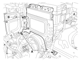
Remove the cover. |
| 3. |
Disconnect the ECM connector (A).
|

| 4. |
Remove the air cleaner assembly.
(Refer to Engine Mechanical System - "Air cleaner" ) |
| 5. |
Remove the battery tray.
(Refer to Engine Electrical System - "Battery") |
| 6. |
Remove the ECM bracket installation bolts (A) and nut (B).
|
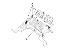
| 7. |
After removing the installation nuts (A), remove the ECM (B) from the bracket.
|
| Installation |
When replacing the ECM, the vehicle equipped with the immobilizer must be performed procedure as below.
[In the case of installing used ECM]
[In the case of installing new ECM]
Perform "Key teaching" procedure with GDS.
(Refer to Body Electrical System - "Immobilizer System")
|
When replacing the ECM, the vehicle equipped with the smart key system (Button start) must be performed procedure as below.
[In the case of installing used ECM]
[In the case of installing new ECM]
Insert the key (or press the start button) and turn it to the
IGN ON and OFF position. Then the ECM learns the smart key information
automatically.
|
| 1. |
Install in the reverse order of removal.
|
| ECM Problem Inspection Procedure |
| 1. |
TEST ECM GROUND CIRCUIT: Measure resistance between ECM and
chassis ground using the backside of ECM harness connector as ECM side
check point. If the problem is found, repair it.
|
| 2. |
TEST ECM CONNECTOR: Disconnect the ECM connector and visually
check the ground terminals on ECM side and harness side for bent pins
or poor contact pressure. If the problem is found, repair it. |
| 3. |
If problem is not found in Step 1 and 2, the ECM could be
faulty. If so, replace the ECM with a new one, and then check the
vehicle again. If the vehicle operates normally then the problem was
likely with the ECM. |
| 4. |
RE-TEST THE ORIGINAL ECM: Install the original ECM (may be
broken) into a known-good vehicle and check the vehicle. If the problem
occurs again, replace the original ECM with a new one. If problem does
not occur, this is intermittent problem.
(Refer to “Intermittent Problem Inspection Procedure” in Basic Inspection Procedure)
|
The programmed VIN cannot be changed. When writing the VIN, confirm the VIN carefully |
| 1. |
Select "VIN Writing" function in "Vehicle S/W Management". |
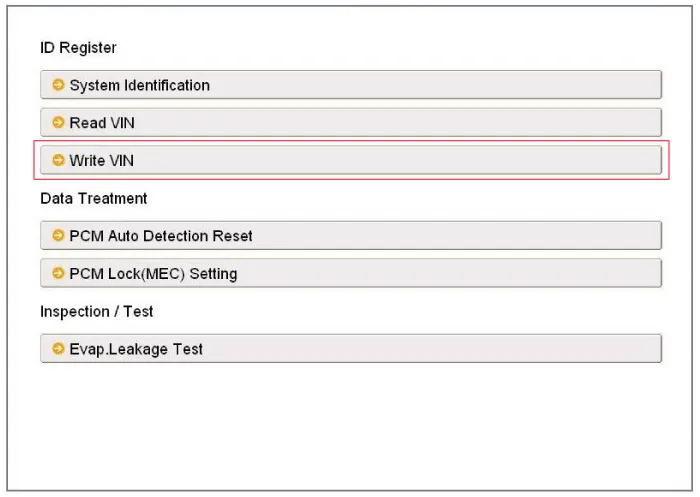
| 2. |
Select "Write VIN" in "ID Register".
|
| 3. |
Input the VIN.
|

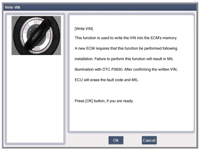
| 4. |
Turn the ignition switch OFF, then back ON. |
ECM Terminal And Input/Output signal ECM Terminal Function Connector [E600-A] Pin No.DescriptionConnected to1- 2- 3- 4Immobilizer Lamp control outputImmobilizer Lamp [Without Button Engine Start System]5Power groundChassis Ground6Power groundChassis Ground7- 8- 92nd CAN [High]Multi-Purpose Check Connector10CAN [High]Other control module, Data Link Connector (DLC), Multi-Purpose Check Connector11Fuel Tank Pressure Sensor (FTPS) signal inputFuel Tank Pressure Sensor (FTPS)12Electrical Load signal inputHead Lamp Relay13- 14Sensor power (+5V)Accelerator Position Sensor (APS) 115Sensor power (+5V)A/C Pressure Transducer (APT)Rail Pressure Sensor (RPS)16Fuel Level Sender (FLS) signal inputFuel Level Sender (FLS)17-18- 19- 20A/C Compressor relay signal outputA/C Control Module21Brake Switch 2 signal inputBrake Switch22- 23- 24Alternator PWM signal input [FR]Alternator25-26- 27Battery power (B+)Ignition Switch28Rail Pressure Sensor (RPS) signal inputRail Pressure Sensor (RPS)29- 30Power groundChassis Ground31- 32- 33- 342nd CAN [Low]Multi-Purpose Check Connector35CAN [Low]Other control module, Data Link Connector (DLC), Multi-Purpose Check Connector36- 37Sensor groundRail Pressure Sensor (RPS)38Accelerator Position Sensor (APS) 1 signal inputAccelerator Position Sensor (APS) 139- 40- 41-42A/C Switch "ON" signal inputA/C Control Module43Brake Switch 1 signal inputBrake Switch44- 45- 46- 47- 48-49- 50- 51- 52Battery power (B+)Battery53- 54- 55Power groundChassis Ground56- 57A/C Compressor Clutch Relay control outputA/C Control Module [With Immobilzer]58- 59Sensor groundAccelerator Position Sensor (APS) 260Sensor groundAccelerator Position Sensor (APS) 161Sensor groundFuel Tank Pressure Sensor (FTPS)62GroundCruise Control Switch63Sensor groundA/C Pressure Transducer (APT)64- 65Sensor Power (+5V)Fuel Tank Pressure Sensor (FTPS)66Cruise Control Switch signal inputCruise Control Switch67A/C Pressure Transducer (APT) signal inputA/C Pressure Transducer (APT)68Accelerator Position Sensor (APS) 2 signal inputAccelerator Position Sensor (APS) 269-70Engine speed signal outputPower Distribution Module (PDM)71Cooling Fan Relay [High] control outputCooling Fan Relay [High]72Alternator PWM signal output (COM)Alternator73- 74Immobilizer communication lineSmart Key Control Module [With Button Engine Start System]Immobilizer Control Unit [Without Button Engine Start System]75Battery power (B+)Main Relay76- 77Battery power (B+)Battery78-79- 80Power groundChassis ground81- 82- 83- 84- 85- 86- 87LIN (Local Interconnect Network) Serial Bus LineBattery Sensor88- 89- 90Sensor power (+5V)Accelerator Position Sensor (APS) 291Cooling Fan Relay [Low] control outputCooling Fan Relay [Low]92- 93Starter Relay control outputStarter Relay94Main Relay control outputMain Relay95Fuel pump Relay control outputFuel pump Relay 96Canister Close Valve (CCV) control outputCanister Close Valve (CCV)97- 98- 99Battery power (B+)Main Relay100Battery power (B+)Main Relay Connector [C600-B] Pin No.
IDB terminal and Inoutput IDB terminal function Connector [C602] Pin No.DescriptionConnected to1- 2- 3- 4- 5- 6- 7- 8- 9- 10- 11- 12- 13- 14- 15- 16Injector (Cylinder #3) [Low] control outputInjector (Cylinder #3)17Injector (Cylinder #6) [Low] control outputInjector (Cylinder #6)18Injector (Cylinder #6) [High] control outputInjector (Cylinder #6)19Injector (Cylinder #2) [Low] control outputInjector (Cylinder #2)20Injector (Cylinder #5) [Low] control outputInjector (Cylinder #5)21- 22Injector (Cylinder #2) signal inputEngine Control Module (ECM)23Injector (Cylinder #5) signal inputEngine Control Module (ECM)24- 25Fuel Pressure Control Valve (FPRV) logic inputEngine Control Module (ECM)26CCP-CAN [Low]Other control module, Data Link Connector (DLC), Multi-purpose check connector27CCP-CAN [High]Other control module, Data Link Connector (DLC), Multi-purpose check connector28Battery power (B+)Ignition switch29Battery power (B+)Main relay30Battery power (B+)Main relay31Injector (Cylinder #4) [High] control outputInjector (Cylinder #4)32Injector (Cylinder #1) [High] control outputInjector (Cylinder #1)33Injector (Cylinder #3) [High] control outputInjector (Cylinder #3)34Injector (Cylinder #2) [High] control outputInjector (Cylinder #2)35Injector (Cylinder #5) [High] control outputInjector (Cylinder #5)36- 37- 38Injector (Cylinder #3) signal inputEngine Control Module (ECM)39- 40Injector (Cylinder #6) signal inputEngine Control Module (ECM)41Injector (Cylinder #4) signal inputEngine Control Module (ECM)42Battery power (B+)Ignition switch43Battery power (B+)Main relay44Battery power (B+)Main relay45Fuel Pressure Control Valve (FPRV) [High] control outputFuel Pressure Control Valve (FPRV)46Injector (Cylinder #4) [Low] control outputInjector (Cylinder #4)47Injector (Cylinder #1) [Low] control outputInjector (Cylinder #1)48ECM groundChassis ground49ECM groundChassis ground50ECM groundChassis ground51- 52ECM groundChassis ground53ECM groundChassis ground54- 55Injector (Cylinder #1) signal inputEngine Control Module (ECM)56- 57- 58- 59Battery power (B+)Main relay60Fuel Pressure Control Valve (FPRV) [Low] control outputFuel Pressure Control Valve (FPRV) IDB Terminal input/output signal Connector [C602] Pin No.
Other information:
Kia Cadenza YG 2016-2021 Service Manual: Components and Components Location
C
Kia Cadenza YG 2016-2021 Service Manual: Blind Spot Detection Unit Repair procedures
Removal 1. Disconnect the negative (-) battery terminal. 2. Remove the rear bumper. (Refer to Body - "Rear Bumper") 3. Remove the BSD unit (A) after loosening the mounting screws. Take care not to separate the bracket from rear bumper when removing the BSD sensor.
Categories
- Manuals Home
- Kia Cadenza Owners Manual
- Kia Cadenza Service Manual
- Suspension System
- Engine And Transmission Assembly
- Emission Control System
- New on site
- Most important about car
