Kia Cadenza YG: Engine Control System / ETC (Electronic Throttle Control) System Specifications
| Specification |
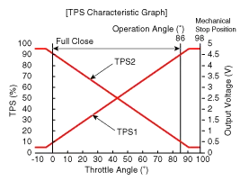
| Throttle angle(°) | Output Voltage (V) [Ref=5V] | |
| TPS1 | TPS2 | |
| 0 | 0.5 | 4.5 |
| 10 | 0.96 | 4.05 |
| 20 | 1.41 | 3.59 |
| 30 | 1.87 | 3.14 |
| 40 | 2.32 | 2.68 |
| 50 | 2.78 | 2.23 |
| 60 | 3.23 | 1.77 |
| 70 | 3.69 | 1.32 |
| 80 | 4.14 | 0.86 |
| 90 | 4.6 | 0.41 |
| 98 | 4.65 | 0.35 |
| C.T (0) | 0.5 | 4.5 |
| W.O.T (86) | 4.41 | 0.59 |
| Item | Specification |
| Coil Resistance (Ω) | 0.3 ~100 [20°C(68°F)] |
Fail-Safe Mode ItemFail-SafeETC MotorThrottle valve stuck at 7°TPSTPS 1 faultECM looks at TPS2TPS 2 faultECM looks at TPS1TPS 1,2 faultThrottle valve stuck at 7°APSAPS 1 faultECM looks at APS 2APS 2 faultECM looks at APS 1APS 1,2 faultEngine idle state When throttle value is stuck at 7°, engine speed is limited at below 1,500rpm and vehicle speed at maximum 40 ~ 50 km/h (25 ~ 31 mph)
Circuit Diagram
Other information:
Kia Cadenza YG 2016-2021 Service Manual: Blind Spot Detection Unit Repair procedures
Removal 1. Disconnect the negative (-) battery terminal. 2. Remove the rear bumper. (Refer to Body - "Rear Bumper") 3. Remove the BSD unit (A) after loosening the mounting screws. Take care not to separate the bracket from rear bumper when removing the BSD sensor.
Kia Cadenza YG 2016-2021 Service Manual: Specifications
Specification Air Conditioner ItemSpecificationCompressorType6VSX16Oil type & CapacityPAG OIL 100±10Pulley type6PK-TYPEDisplacement160cc/revCondenserHeat rejection14,400 ±5% kcal/hrA/C Pressure transducerThe method to measure the pressureVoltage= 0.
Categories
- Manuals Home
- Kia Cadenza Owners Manual
- Kia Cadenza Service Manual
- Engine Mechanical System
- Restraint
- Body (Interior and Exterior)
- New on site
- Most important about car
