Kia Cadenza YG: Engine Control System / Injector Drive Box (IDB) Repair procedures
| Removal |
| 1. |
Turn the ignition switch off and disconnect the battery negative (-) cable. |
| 2. |
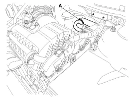
Disconnect the injector drive box (IDB) connector (A).
|
| 3. |
Remove the air cleaner assembly.
(Refer to Engine Mechanical System - "Air Cleaner") |
| 4. |
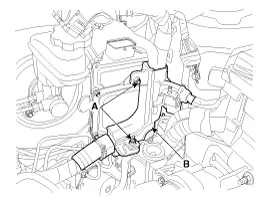
Remove the main wiring harness (B) after removing the nut (A).
|
| 5. |
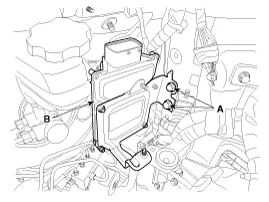
Remove the IDB bracket assembly (B) after removing the bolts (A).
|
| 6. |
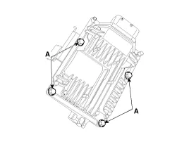
After removing the installation bolts (A), remove the IDB from the bracket.
|
| Installation |
| 1. |
Install in the reverse order of removal.
|
IDB terminal and Inoutput IDB terminal function Connector [C602] Pin No.DescriptionConnected to1- 2- 3- 4- 5- 6- 7- 8- 9- 10- 11- 12- 13- 14- 15- 16Injector (Cylinder #3) [Low] control outputInjector (Cylinder #3)17Injector (Cylinder #6) [Low] control outputInjector (Cylinder #6)18Injector (Cylinder #6) [High] control outputInjector (Cylinder #6)19Injector (Cylinder #2) [Low] control outputInjector (Cylinder #2)20Injector (Cylinder #5) [Low] control outputInjector (Cylinder #5)21- 22Injector (Cylinder #2) signal inputEngine Control Module (ECM)23Injector (Cylinder #5) signal inputEngine Control Module (ECM)24- 25Fuel Pressure Control Valve (FPRV) logic inputEngine Control Module (ECM)26CCP-CAN [Low]Other control module, Data Link Connector (DLC), Multi-purpose check connector27CCP-CAN [High]Other control module, Data Link Connector (DLC), Multi-purpose check connector28Battery power (B+)Ignition switch29Battery power (B+)Main relay30Battery power (B+)Main relay31Injector (Cylinder #4) [High] control outputInjector (Cylinder #4)32Injector (Cylinder #1) [High] control outputInjector (Cylinder #1)33Injector (Cylinder #3) [High] control outputInjector (Cylinder #3)34Injector (Cylinder #2) [High] control outputInjector (Cylinder #2)35Injector (Cylinder #5) [High] control outputInjector (Cylinder #5)36- 37- 38Injector (Cylinder #3) signal inputEngine Control Module (ECM)39- 40Injector (Cylinder #6) signal inputEngine Control Module (ECM)41Injector (Cylinder #4) signal inputEngine Control Module (ECM)42Battery power (B+)Ignition switch43Battery power (B+)Main relay44Battery power (B+)Main relay45Fuel Pressure Control Valve (FPRV) [High] control outputFuel Pressure Control Valve (FPRV)46Injector (Cylinder #4) [Low] control outputInjector (Cylinder #4)47Injector (Cylinder #1) [Low] control outputInjector (Cylinder #1)48ECM groundChassis ground49ECM groundChassis ground50ECM groundChassis ground51- 52ECM groundChassis ground53ECM groundChassis ground54- 55Injector (Cylinder #1) signal inputEngine Control Module (ECM)56- 57- 58- 59Battery power (B+)Main relay60Fuel Pressure Control Valve (FPRV) [Low] control outputFuel Pressure Control Valve (FPRV) IDB Terminal input/output signal Connector [C602] Pin No.
Description The Electronic Throttle Control (ETC) System consists of a throttle body with an integrated control motor and throttle position sensor (TPS).
Other information:
Kia Cadenza YG 2016-2021 Service Manual: Repair procedures
Removal 1. Remove the trunk trim in the trunk after removing the screws and clips. (Refer to Body - "Trunk") 2. Remove the camera holder (A) as shown arrow direction, and then remove the back view camera (B). Installation 1. Install the back view camera and camera holder.
Kia Cadenza YG 2016-2021 Service Manual: Ambient Sensor Repair procedures
Inspection 1. Ignition "OFF" 2. Disconnect ambient temperature sensor. 3. Check the resistance of ambient temperature sensor between terminals 1 and 2 whether it is changed by changing of the ambient temperature. 1. Sensor Ground2.
Categories
- Manuals Home
- Kia Cadenza Owners Manual
- Kia Cadenza Service Manual
- Body Electrical System
- Schematic Diagrams
- Engine Mechanical System
- New on site
- Most important about car
