Kia Cadenza YG: Clutch & Brake / Components and Components Location
| Components Location |
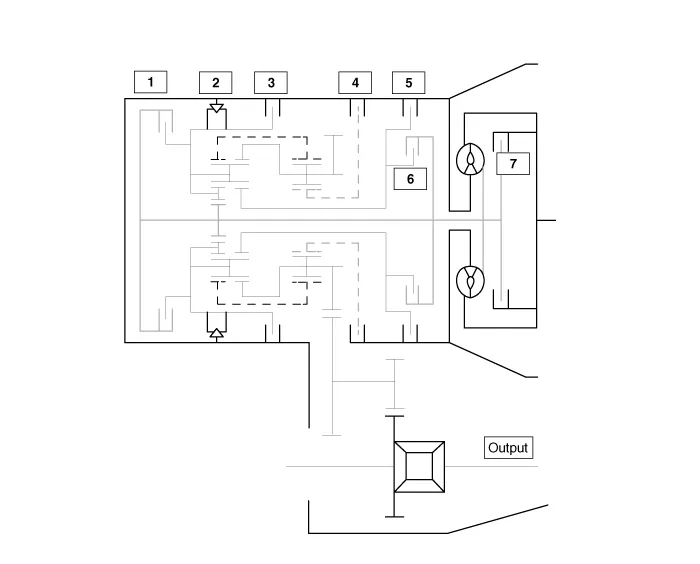
| 1. Overdrive clutch (OD/C) 2. One way clutch (OWC) 3. Low & Reverse brake (LR/B) 4. Underdrive brake (UD/B) | 5. 26 brake(26/B) 6. 35R clutch (35R/C) 7. Damper clutch (D/C) |
Description The 6-speed automatic transaxle consists of an overdrive clutch (OD/C), a one-way clutch (OWC), a lower and reverse brake (LR/B), an underdrive brake (UD/B), a 26 brake (26/B), and a 35R clutch (35R/C).
Power Flow Chart P,NUD/BLR/B26/B35R/COD/COWC● ▣ Direction of Rotation ▶Lower & Reverse Brake (LR/B) Activation → Overdrive (O/D) Hub Lock → Mid & Rear P/C Lock ▶Input Shaft Rotation → Rear Sun Gear Rotation → Rear Inner Pinion Rotation (Reverse) → Rear Outer Pinion Rotation → Rear Annulus Gear Rotation → Front Annulus Gear Rotation → Front Pinion Rotation → Front Sun Gear Rotation (Reverse) → Underdrive (U/D) Hub Rotation (Reverse) ▶Input shaft rotation → Overdrive Clutch (OD/C) Retainer Rotation ▶Input shaft rotation → 35R Clutch Rotation RUD/BLR/B26/B35R/COD/COWC●● ▣ Power Delivery Route ▶ Middle carrier locked and middle sun gear in rotation ▶ Rotating the middle planetary gear''s sun gear while its carrier is locked in place slows down and reverse rotates the annulus gear (front carrier), resulting in power transfer to the front carrier.
Other information:
Kia Cadenza YG 2016-2021 Service Manual: Repair procedures
Diagnosis With GDS 1. BSD system defects can be quickly diagnosed with the GDS. GDS operates actuator quickly to monitor, input/output value and self diagnosis. 2. Connect the cable of GDS to the data link connector in driver side crash pad lower panel, turn the power on GDS.
Kia Cadenza YG 2016-2021 Service Manual: Temperature Control Actuator Description and Operation
D
Categories
- Manuals Home
- Kia Cadenza Owners Manual
- Kia Cadenza Service Manual
- Battery Troubleshooting
- Body (Interior and Exterior)
- Schematic Diagrams
- New on site
- Most important about car
