Kia Cadenza YG: AVN System / Components and Components Location
| Components Location |
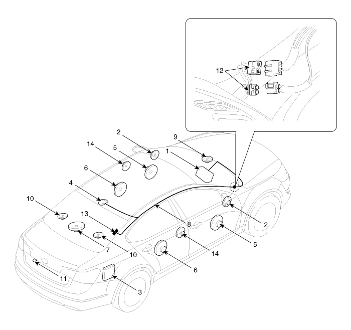
| 1. AVN (A/V & Navigation head unit) 2. Front tweeter speaker 3. External amplifier 4. Roof antenna 5. Front door speaker 6. Rear door speaker 7. Sub woofer speaker | 8. Antenna feeder cable 9. Front center speaker 10. Surround speaker 11. Back view camera 12. Feeder cable joint connector 13. Glass antenna (Radio) 14. Rear tweeter speaker |
Specifications AVN Head Unit ItemSpecificationPower sourceDC 14.4V (-) groundFrequency range / Channel spaceFM : 87.5 ~ 107.9 MHz / 200 KHzAM : 530 ~ 1710 KHz / 10 KHzTuning typePLL SYNTHESIZED TUNINGImpedance2 ohm x 4Antenna80 pF 75 OhmDark currentMax.
System Block Diagram
Other information:
Kia Cadenza YG 2016-2021 Service Manual: Blind Spot Detection Variant Coding Description and Operation
Description The used radar frequency of BSD is two, "North America region" and "Except North America region". If it replaces BSD unit, BSD unit has to perform the procedure of variant coding. BSD Variant Coding 1. Select the "BSD Variant Coding" procedure in BSD system.
Kia Cadenza YG 2016-2021 Service Manual: Troubleshooting
Troubleshooting Problem Symptoms Table Before replacing or repairing air conditioning components, first determine if the malfunction is due to the refrigerant charge, air flow or compressor. Use the table below to help you find the cause of the problem.
Categories
- Manuals Home
- Kia Cadenza Owners Manual
- Kia Cadenza Service Manual
- Steering System
- Specifications
- Restraint
- New on site
- Most important about car
