Kia Cadenza YG: Ignition System / Ignition Coil Repair procedures
| Removal |
| 1. |
Turn the ignition switch OFF and disconnect the battery negative (-) cable. |
| 2. |
Remove the engine cover. |
| 3. |
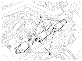
Disconnect the ignition coil connector (A). |
| 4. |
Remove the ignition coil after loosening the bolts (B).
|


| 1. |
Turn the ignition switch OFF and disconnect the battery negative (-) cable. |
| 2. |
Remove the engine cover. |
| 3. |
Remove the surge tank assembly.
(Refer to Engine Mechanical System - "Surge Tank") |
| 4. |
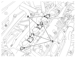
Disconnect the ignition coil connector (A). |
| 5. |
Remove the igniton coil after loosening the bolts (B).
|
| Installation |
| 1. |
Install in the reverse order of removal.
|
| Inspection |
| 1. |
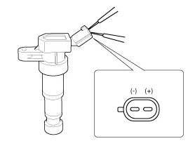
Measure the primary coil resistance between terminals (+) and (-).
|
Circuit Diagram
Description A spark plug is a device for delivering electric current from an ignition system to the combustion chamber of a spark-ignition engine to ignite the compressed fuel/air mixture therein by means of an electric spark, while containing combustion pressure within the engine.
Other information:
Kia Cadenza YG 2016-2021 Service Manual: A/C Pressure Transducer Repair procedures
Inspection 1. Measure the pressure of high pressure line by measuring voltage output between NO.1 and NO.2 terminals. 2. Inspect the voltage value whether it is sufficient to be regular value or not. Voltage = 0.00878835 * Pressure + 0.37081095 [PSIA] 3.
Kia Cadenza YG 2016-2021 Service Manual: Photo Sensor Description and Operation
Description 1. The photo sensor is located at the center of defrost nozzle. 2. The photo sensor contains a photovoltaic (sensitive to sunlight) diode. The solar radiation received by its light receiving portion, generates an electromotive force in proportion to the amount of radiation received which is transferred to the automatic tem
Categories
- Manuals Home
- Kia Cadenza Owners Manual
- Kia Cadenza Service Manual
- Components and Components Location
- Restraint
- Battery Troubleshooting
- New on site
- Most important about car
