
Kia Cadenza YG: Lubrication System / Oil Pressure Switch Repair procedures
Kia Cadenza YG 2016-2021 Service Manual / Engine Mechanical System / Lubrication System / Oil Pressure Switch Repair procedures
| Removal and Installaion |
| 1. |
Remove the intake manifold.
(Refer to Intake And Exhaust System - "Intake Manifold") |
| 2. |
Remove the delivery pipe and injector.
(Refer to Engine Control / Fuel System - "Delivery Pipe") |
| 3. |
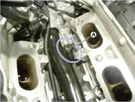
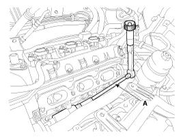
Remove the oil pressure switch (A) after disconnecting the connector.
|

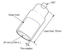
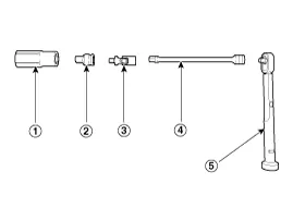
 24mm deep socket
 1/2" to 3/8" drive socket adapter (only if using 1/2" drive deep socket)
 3/8" universal joint
 3/8" extension bar
 Socket wrench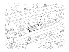
| 4. |
Install in the reverse order of removal.
|
| Inspection |
| 1. |
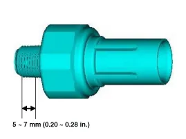
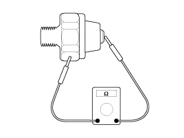
Check the continuity between the terminal and the body with an ohmmeter.
If there is no continuity, replace the oil pressure switch.
|
| 2. |
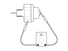
Check the continuity between the terminal and the body when
the fine wire is pushed. If there is continuity even when the fine wire
is pushed, replace the switch.
|
| 3. |
If there is no continuity when a 50 kpa (7psi) is applied
through the oil hole the switch is operaing properly. Check for air
leakage. If air leaks, the diaphragm is broken. Replace it. |
Components 1. Oil cover2. Oil cover gasket3. Oil pressure switch
Components 1. Oil level gauge2. Oil level gauge pipe3. O-ring
Other information:
Kia Cadenza YG 2016-2021 Service Manual: Repair procedures
Refrigerant System Service Basics Refrigerant Recovery Use only service equipment that is U.L-listed and is certified to meet the requirements of SAE J2210 to remove HFC-134a(R-134a) from the air conditioning system. – Air conditioning refrigerant or lubricant vapor can irritate your eyes, nose, or th
Kia Cadenza YG 2016-2021 Service Manual: Ambient Sensor Description and Operation
Description 1. The ambient temperature sensor is located at the front of the condenser and detects ambient air temperature. It is a negative type thermistor resistance will increase with lower temperature, and decrease with higher temperatures.
Categories
- Manuals Home
- Kia Cadenza Owners Manual
- Kia Cadenza Service Manual
- Emission Control System
- Specifications
- Engine Mechanical System
- New on site
- Most important about car

Copyright © 2026 www.kcadenzavg.com - 0.0233