Kia Cadenza YG: Cylinder Block / Piston and Connecting Rod Components and Components Location
| Components |
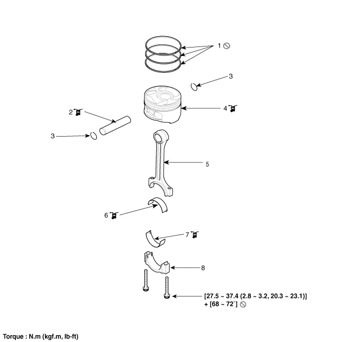
| 1. Piston ring 2. Piston pin 3. Snap ring 4. Piston | 5. Connecting rod 6. Connecting rod upper bearing 7. Connecting rod lower bearing 8. Connecting rod bearing cap |
Removal 1. Remove the transaxle assembly. (Refer to Automatic Transaxle System - "Automatic Transaxle") 2. Remove the drive plate. (Refer to Cylinder Block - "Drive Plate") 3.
Disassembly • Use fender covers to avoid damaging painted surfaces. • To avoid damage, unplug the wiring connectors carefully while holding the connector portion.
Other information:
Kia Cadenza YG 2016-2021 Service Manual: Adaptive Front Lighting System Repair procedures
Removal 1. Disconnect the negative (-) battery terminal. 2. Using a screwdriver or remover, remove the crash pad side cover (A). [RH] 3. Disconnect the stopper (B) from the glove box (A). 4. Disconnect the air damper (A) from the glove box (B).
Kia Cadenza YG 2016-2021 Service Manual: Description and Operation
Description Back view camera will activate when the backup light is ON with the ignition switch ON and the shift lever in the R position. This system is a supplemental system that shows behind the vehicle through the ECM (Reverse Display Room Mirror) mirror or AVN head unit while backing-up.
Categories
- Manuals Home
- Kia Cadenza Owners Manual
- Kia Cadenza Service Manual
- Transaxle Control Module (TCM) Repair procedures
- Body (Interior and Exterior)
- Alternator Schematic Diagrams
- New on site
- Most important about car
