
Kia Cadenza YG: Rear Suspension System / Rear Shock Absorber Repair procedures
| Replacement |
| 1. |
Remove the rear wheel & tire.
|

| 2. |
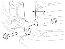
Loosen the bolt & nut and then disconnect the shock absorber (A) with the rear axle.
|
| 3. |
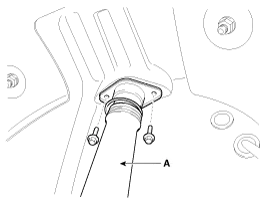
Loosen the shock absorber (A) mounting bolts.
|
| 4. |
Installation is the reverse of removal. |
| 1. |
Check the rubber parts for wear and deterioration. |
| 2. |
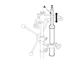
Compress and extend the piston rod (A) and check that there is no abnormal resistance or unusual sound during operation.
|
Components 1. Self locking nut2. Bracket assembly3. Bumper rubber4. Dust cover5. Shock absorber
Removal 1. Remove the rear wheel & tire. Tightening torque: 88.3 ~ 107.9N.m (9.0 ~ 11.0kgf.m, 65.1 ~ 79.6lb-ft) Be careful not to damage to the hub bolts when removing the rear wheel & tire.
Other information:
Kia Cadenza YG 2016-2021 Service Manual: Blower Unit Repair procedures
Replacement 1. Disconnect the negative (-) battery terminal. 2. Remove the heater and blower unit.(Refer to HA group – heater unit). 3. Remove the blower unit (A) from the heater unit after loosening a mounting bolt and 3 screws. Make sure that there is no air leaking out of the blower and duct joints.
Kia Cadenza YG 2016-2021 Service Manual: Climate Control Air Filtar Repair procedures
Replacement 1. Disconnect the damper (B) from the glove box (A) and then remove the glove box lift (C). 2. Remove the filter cover (A) with pushing the knob. 3. Replace the air filter (B), install it after making sure of the direction of air filter.
Categories
- Manuals Home
- Kia Cadenza Owners Manual
- Kia Cadenza Service Manual
- Suspension System
- Engine Mechanical System
- Body (Interior and Exterior)
- New on site
- Most important about car
