Kia Cadenza YG: Rear Suspension System / Rear Upper Arm Repair procedures
| Removal |
| 1. |
Remove the rear wheel & tire.
|

| 2. |
Remove the rear shock absorber.
(Refer to Rear Suspension System - “Rear Shock Absorber”) |
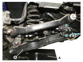
| 3. |
Set up the transmission jack (A) under the lower arm (B).
|
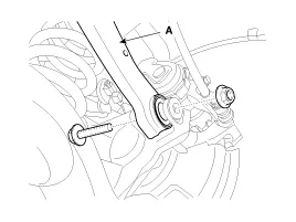
| 4. |
Loosen the bolt & nut and then remove the rear upper arm (A) with the rear axle.
|
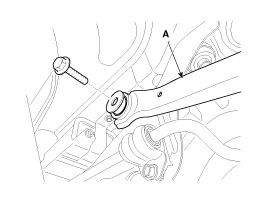
| 5. |
Loosen the bolt & nut and then remove the rear upper arm (A) with the sub frame.
|
| Installation |
| 1. |
Installation is the reverse of removal.
|
| Inspection |
| 1. |
Check the bushing for wear and deterioration. |
| 2. |
Check the rear lower arm for deformation. |
| 3. |
Check the coil spring and spring pad for deterioration and deformation. |
| 4. |
Check for all bolts and nut. |
Replacement 1. Remove the rear wheel & tire. Tightening torque: 88.3 ~ 107.9N.m (9.0 ~ 11.0kgf.m, 65.1 ~ 79.6lb-ft) Be careful not to damage to the hub bolts when removing the rear wheel & tire.
Removal 1. Remove the rear wheel & tire. Tightening torque: 88.3 ~ 107.9N.m (9.0 ~ 11.0kgf.m, 65.1 ~ 79.6lb-ft) Be careful not to damage to the hub bolts when removing the rear wheel & tire.
Other information:
Kia Cadenza YG 2016-2021 Service Manual: Blind Spot Detection Unit Repair procedures
Removal 1. Disconnect the negative (-) battery terminal. 2. Remove the rear bumper. (Refer to Body - "Rear Bumper") 3. Remove the BSD unit (A) after loosening the mounting screws. Take care not to separate the bracket from rear bumper when removing the BSD sensor.
Kia Cadenza YG 2016-2021 Service Manual: Repair procedures
Refrigerant System Service Basics Refrigerant Recovery Use only service equipment that is U.L-listed and is certified to meet the requirements of SAE J2210 to remove HFC-134a(R-134a) from the air conditioning system. – Air conditioning refrigerant or lubricant vapor can irritate your eyes, nose, or th
Categories
- Manuals Home
- Kia Cadenza Owners Manual
- Kia Cadenza Service Manual
- Steering System
- Suspension System
- Body (Interior and Exterior)
- New on site
- Most important about car
