
Kia Cadenza YG: Rear Suspension System / Rear Lower Arm Repair procedures
Kia Cadenza YG 2016-2021 Service Manual / Suspension System / Rear Suspension System / Rear Lower Arm Repair procedures
| Removal |
| 1. |
Remove the rear wheel & tire.
|

| 2. |
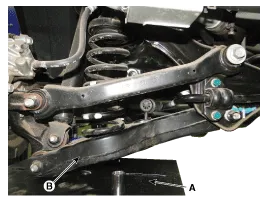
Set up the transmission jack (A) under the lower arm (B).
|
| 3. |
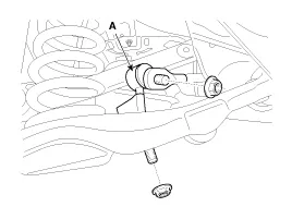
Loosen the nut and then remove the rear stabilizer link (A) from the lower arm and subframe.
|
| 4. |
Loosen the bolt & nut and then remove the rear lower arm (A) with the rear axle.
|

| 5. |
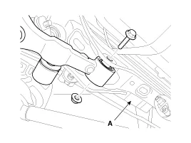
Loosen the bolt & nut and then remove the rear lower arm (A) from the sub frame.
|
| Inspection |
| 1. |
Check the bushing for wear and deterioration. |
| 2. |
Check the rear lower arm for deformation. |
| 3. |
Check the coil spring and spring pad for deterioration and deformation. |
| 4. |
Check for all bolts and nut. |
Removal 1. Remove the rear wheel & tire. Tightening torque: 88.3 ~ 107.9N.m (9.0 ~ 11.0kgf.m, 65.1 ~ 79.6lb-ft) Be careful not to damage to the hub bolts when removing the rear wheel & tire.
Replacement 1. Remove the rear wheel & tire. Tightening torque: 88.3 ~ 107.9N.m (9.0 ~ 11.0kgf.m, 65.1 ~ 79.6lb-ft) Be careful not to damage to the hub bolts when removing the rear wheel & tire.
Other information:
Kia Cadenza YG 2016-2021 Service Manual: Repair procedures
Inspection Initialization and diagnosis sequence by using diagnostic equipment Below content summarize the procedure for A/S using Diagnostic equipment Download Parameter 1. Select "AFLS" menu after selecting a vehicle. 2. Select "Parameter download" menu for define a characteristc of vehicle.
Kia Cadenza YG 2016-2021 Service Manual: Intake Actuator Description and Operation
D
Categories
- Manuals Home
- Kia Cadenza Owners Manual
- Kia Cadenza Service Manual
- Engine Electrical System
- Timing Chain Repair procedures
- Restraint
- New on site
- Most important about car

Copyright © 2026 www.kcadenzavg.com - 0.0229