
Kia Cadenza YG: Rear Suspension System / Rear Stabilizer Bar Repair procedures
| Replacement |
| 1. |
Remove the rear wheel & tire.
|

| 2. |
Loosen the nut and then remove the rear stabilizer link (B) with the rear lower arm (A).
|

| 3. |
Loosen the nut and then remove the stabilizer link (A) with the rear stabilizer bar.
|
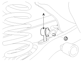
| 4. |
Loosen the mounting bolt and then remove the stabilizer bar (B) with the sub frame (A).
|

| 5. |
Installation is the reverse of removal. |
| Inspection |
| 1. |
Check the rear stabilizer bar for deformation. |
| 2. |
Check the rear stabilizer link ball joint for damage. |
Removal 1. Remove the rear wheel & tire. Tightening torque: 88.3 ~ 107.9N.m (9.0 ~ 11.0kgf.m, 65.1 ~ 79.6lb-ft) Be careful not to damage to the hub bolts when removing the rear wheel & tire.
Replacement 1. Remove the rear wheel & tire. Tightening torque: 88.3 ~ 107.9N.m (9.0 ~ 11.0kgf.m, 65.1 ~ 79.6lb-ft) Be careful not to damage to the hub bolts when removing the rear wheel & tire.
Other information:
Kia Cadenza YG 2016-2021 Service Manual: Antenna Coil Repair procedures
Removal 1. Disconnect the negative (-) battery terminal. 2. Remove the crash pad lower panel. (Refer to Body - "Crash Pad") 3. Disconnect the 6P connector (B) of the coil antenna and then remove the coil antenna (A) after loosening the screw.
Kia Cadenza YG 2016-2021 Service Manual: Blind Spot Detection Unit Repair procedures
Removal 1. Disconnect the negative (-) battery terminal. 2. Remove the rear bumper. (Refer to Body - "Rear Bumper") 3. Remove the BSD unit (A) after loosening the mounting screws. Take care not to separate the bracket from rear bumper when removing the BSD sensor.
Categories
- Manuals Home
- Kia Cadenza Owners Manual
- Kia Cadenza Service Manual
- Timing Chain Repair procedures
- Body Control Module (BCM) Description and Operation
- General Information
- New on site
- Most important about car
