Kia Cadenza YG: Horn / Repair procedures
| Inspection |
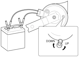
Test the horn by connecting battery voltage to the 1 terminal and ground the 2 terminal.
The horn should make a sound. If the horn fails to make a sound, replace it.
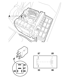
Horn Relay Inspection
| 1. |
Remove the horn relay (A) from the engine room relay box. |
| 2. |
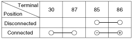
There should be continuity between the No.30 and No.87
terminals when power and ground are connected to the No.85 and No.86
terminals. |
| 3. |
There should be no continuity between the No.30 and No.87 terminals when power is disconnected.
|
| Removal |
| 1. |
Remove the radiator grill upper gide.
(Refer to Body - "Front Bumper") |
| 2. |
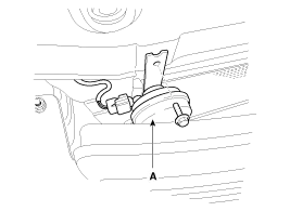
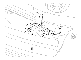
Remove the mounting nut and disconnect the horn connector, then remove the high pitch horn (A) and low pitch horn (B).
|
| Installation |
| 1. |
Connect the horn connector, then reassemble the horn. |
| 2. |
Reassemble the radiator grill upper gide. |
| Adjustment |
Operate the horn, and adjust the tone to a suitable level by turning the adjusting screw.
After adjustment, apply a small amount of paint around the screw head to keep it from loosening. |

Component Location 1. Horn switch2. Horn relay (Engine room compartment)3. Horn - High pitch4. Horn - Low pitch5. Clock spring
Other information:
Kia Cadenza YG 2016-2021 Service Manual: Parking Assist Sensor Repair procedures
Removal 1. Disconnect the negative (-) battery terminal. 2. Remove the rear bumper cover. (Refer to Body - "Rear Bumper Cover") 3. Disconnect the connector (A) from the parking assist sensor. 4. Pull out the sensor (A) by opening the sensor holder (B) out.
Kia Cadenza YG 2016-2021 Service Manual: Repair procedures
Diagnosis With GDS 1. BSD system defects can be quickly diagnosed with the GDS. GDS operates actuator quickly to monitor, input/output value and self diagnosis. 2. Connect the cable of GDS to the data link connector in driver side crash pad lower panel, turn the power on GDS.
Categories
- Manuals Home
- Kia Cadenza Owners Manual
- Kia Cadenza Service Manual
- Battery Troubleshooting
- Schematic Diagrams
- Engine Mechanical System
- New on site
- Most important about car

Copyright © 2026 www.kcadenzavg.com - 0.0244