Kia Cadenza YG: Automatic Transaxle Control System / Shift Cable Repair procedures
Kia Cadenza YG 2016-2021 Service Manual / Automatic Transaxle System / Automatic Transaxle Control System / Shift Cable Repair procedures
| Removal |
| 1. |
Remove the center console assembly.
(Refer to Body - "Console") |
| 2. |
Remove the duct (A).
|

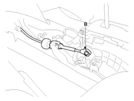
| 3. |
Remove the control cable (B).
|
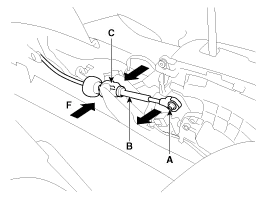
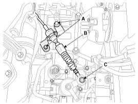
| 4. |
Disconnect the shift cable (A) and then remove the shift
cable (B) after pressing the shift cable socket (C) in the direction of
"F".
|

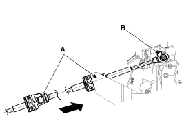
| 5. |
Remove the control cable assembly in the vehicle after removing the nuts (B) and the retainer (A).
|
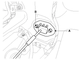
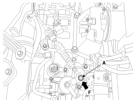
| 6. |
Remove the nut (C). |
| 7. |
Remove the control cable (B) after removing the nut (C) and the bolt (A).
|
| 8. |
Remove the control cable inside of cab.
|
| Installation |
| 1. |
Installation is the reverse of removal.
|
| Adjustment |
| Adjusting method for T/M control cable |
| 1. |
Make sure vehicle does not roll before setting room side
shift lever and Automatic Transaxle(AT) side manual control lever to "N"
position. |
| 2. |
Connect room side shift lever and control cable. |
| 3. |
Push cable to "F" direction shown to eliminate FREE PLAY. |
| 4. |
Tighten adjusting nut (A).
|
| 5. |
After adjusting, check to be sure that this part operates as
designed at each range of Automatic Transaxle(AT) side corresponding to
each position of room lever. |
Components 1. Shift lever knob & Boots assembly2. Shift lever assembly3. Control cable assembly
Other information:
Kia Cadenza YG 2016-2021 Service Manual: Description and Operation
Description System Overview The System offers the following features: – Human / machine interface through a 1-stage button, for terminal switching and engine start. – Control of external relays for ACC / IGN1 / IGN2 terminal switching and STARTER, without use of mechanical ignition switch.
Kia Cadenza YG 2016-2021 Service Manual: Repair procedures
Diagnosis With GDS 1. BSD system defects can be quickly diagnosed with the GDS. GDS operates actuator quickly to monitor, input/output value and self diagnosis. 2. Connect the cable of GDS to the data link connector in driver side crash pad lower panel, turn the power on GDS.
Categories
- Manuals Home
- Kia Cadenza Owners Manual
- Kia Cadenza Service Manual
- Schematic Diagrams
- Restraint
- Body Electrical System
- New on site
- Most important about car

Copyright © 2026 www.kcadenzavg.com - 0.0229