
Kia Cadenza YG: Automatic Transaxle Control System / Torque Converter Control Solenoid Valve (T/CON_VFS) Repair procedures
| Inspection |
| 1. |
Turn ignition switch OFF. |
| 2. |
Remove the battery and battery tray.
(Refer to Engine Electrical System - "Battery") |
| 3. |
Disconnect the solenoid valve connector (A).
|

| 4. |
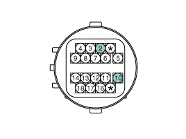
Measure the resistance between power terminal (10) and signal terminal (2).
|
| Removal |
| 1. |
Remove the under cover.
(Refer to Engine Mechanical System - "Engine Room Under Cover") |
| 2. |
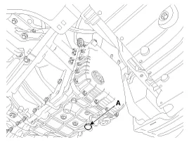
Remove the ATF drain plug (A), allow the fluid to drain out and then reinstall the drain plug.
|

| 3. |
Remove the battery and battery tray.
(Refer to Engine Electrical System - "Battery") |
| 4. |
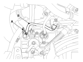
Remove the wiring bracket (A) and the air breather hose (B).
|
| 5. |
Lift the vehicle after loosening valve body cover upper bolts. |
| 6. |
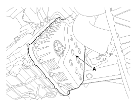
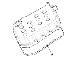
Remove the valve body cover (A) by loosening bolts.
|
| 7. |
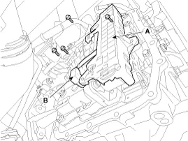
Remove the solenoid valve harness (A) and oil temperature sensor (B) after removing the bolts.
|
| 8. |
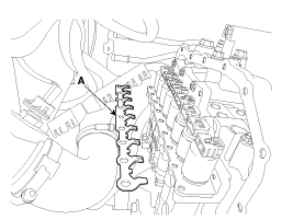
Remove solenoid valve support bracket (A).
|
| 9. |
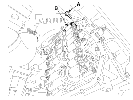
Remove the torque converter control solenoid valve (B) after loosening the bolt (A).
|
| Installation |
| 1. |
Install in the reverse order of removal.
|
Specification Item SpecificationControl typeN/H (Normal High)Control pressure kpa (kgf/cm², psi)"500.14 ~ 9.81 (5.1 ~ 0.1, 72.54 ~ 1.42)"Current value (mA)50 ~ 850Coil resistance(Ω)5.
Other information:
Kia Cadenza YG 2016-2021 Service Manual: Description and Operation
System Overview RPAS (Rear Parking Assist System) is an electronic driving aid that warns the driver to be cautious while parking or in low speed environments. The sensor uses ultrasonic waves to detect objects within proximity of the vehicle.
Kia Cadenza YG 2016-2021 Service Manual: Temperature Control Actuator Repair procedures
Inspection 1. Ignition "OFF" 2. Disconnect the connector of temperature control actuator. 3. Verify that the temperature control actuator operates to the hot position when connecting 12V to the terminal 3 and grounding terminal 7. Verify that the temperature control actuator operates to the cool position when connecting in the rev
Categories
- Manuals Home
- Kia Cadenza Owners Manual
- Kia Cadenza Service Manual
- Suspension System
- Body Control Module (BCM) Description and Operation
- Timing Chain Repair procedures
- New on site
- Most important about car
