Kia Cadenza YG: Tire Pressure Monitoring System / TPMS Sensor Repair procedures
| Removal |
| 1. |
Remove the tire. |
| 2. |
Remove the foreign substance from wheel. |
| 3. |
Discharge the air to the tire air inlet (A).
|

| 4. |
Install the bead brake from the tire and then remove the the tire rim by stepping slide bar, a pedal.
|

| 5. |
Carrying out the operation of the brake beads in various places until the fall tire completely from the rim. |
| 6. |
Put on the wheel turn table and then, fixed to the turntable wheel by stepping slide bar, a pedal. |
| 7. |
Install the rim of the wheel head mounting and then fixed.
|


| 8. |
Install the lever and then located to top tire between.
|

| 9. |
By stepping turntable pedal, rotated clockwise the turntable and then separate from the wheel outside the tire. |
| 10. |
Inside of the tire, it is to remove the tire from the wheel in the same way as No. 10.
|

| 11. |
Install in the reverse order of removal. |
| Installation |
|
| 1. |
Assemble valve to sensor and turn valve 3 times with the square part of the screw in the slot.
|
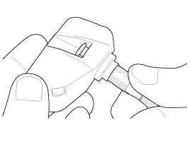
| 2. |
Mount assembly to wheel.
|
| 3. |
Tighten washer and nut by hand until the valve thread meets the nut built-in calibrated stop.
|

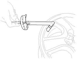
| 4. |
Using a torque wrench, tighten the nut to 5.9±0.74 lb-ft
(8.0±1.0 Nm) It is normal to feel a break as the 1.7 lb-ft (2.3Nm)
calibrated stop in the nut snaps and the torque falls.
|
|
| Sensor ID Writing (Wireless) |


| Sensor ID Writing |


Description 1. Mode (1) Configuration State • All sensors should be in the Low Line state. • In High Line configuration, sensor transmissions occur every 1 minute (nominal) and pressure is measured every 4 seconds.
Description 1. Mode (1) Virgin State • The receiver as a sole part is shipped in this state. Replacement parts should therefore arrive in this state.
Other information:
Kia Cadenza YG 2016-2021 Service Manual: A/C Pressure Transducer Repair procedures
Inspection 1. Measure the pressure of high pressure line by measuring voltage output between NO.1 and NO.2 terminals. 2. Inspect the voltage value whether it is sufficient to be regular value or not. Voltage = 0.00878835 * Pressure + 0.37081095 [PSIA] 3.
Kia Cadenza YG 2016-2021 Service Manual: Photo Sensor Description and Operation
Description 1. The photo sensor is located at the center of defrost nozzle. 2. The photo sensor contains a photovoltaic (sensitive to sunlight) diode. The solar radiation received by its light receiving portion, generates an electromotive force in proportion to the amount of radiation received which is transferred to the automatic tem
Categories
- Manuals Home
- Kia Cadenza Owners Manual
- Kia Cadenza Service Manual
- Steering System
- Timing Chain Repair procedures
- Brake System
- New on site
- Most important about car
