Kia Cadenza YG: Engine Control System / Manifold Absolute Pressure Sensor (MAPS) Schematic Diagrams
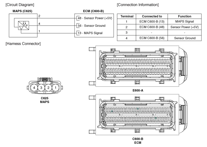
| Circuit Diagram |
Specification Pressure [kPa (kgf/cm², psi)]Output Voltage (V)20.0 (0.20, 2.90)0.7946.66 (0.47, 6.77)1.84101.32 (1.03, 14.7)4.0
Inspection 1. Connect the GDS on the Data Link Connector (DLC). 2. Measure the output voltage of the MAPS at idle and IG ON. ConditionOutput Voltage (V)IG ONApprox.
Other information:
Kia Cadenza YG 2016-2021 Service Manual: Compressor Repair procedures
Removal 1. If the compressor is marginally operable, run the engine at idle speed, and let the air conditioning work for a few minutes, then shut the engine off. 2. Disconnect the negative cable from the battery. 3. Recover the refrigerant with a recovery/charging station.
Kia Cadenza YG 2016-2021 Service Manual: Photo Sensor Description and Operation
Description 1. The photo sensor is located at the center of defrost nozzle. 2. The photo sensor contains a photovoltaic (sensitive to sunlight) diode. The solar radiation received by its light receiving portion, generates an electromotive force in proportion to the amount of radiation received which is transferred to the automatic tem
Categories
- Manuals Home
- Kia Cadenza Owners Manual
- Kia Cadenza Service Manual
- Mode Control Actuator Repair procedures
- Steering System
- Restraint
- New on site
- Most important about car
