Kia Cadenza YG: Blind Spot Detection System / Repair procedures
| Diagnosis With GDS |
| 1. |
BSD system defects can be quickly diagnosed with the GDS. GDS
operates actuator quickly to monitor, input/output value and self
diagnosis. |
| 2. |
Connect the cable of GDS to the data link connector in driver side crash pad lower panel, turn the power on GDS. |
| 3. |
Select the vehicle model and then BSD system. |
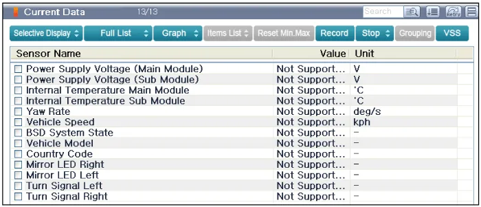
| 4. |
Select "Input/output monitoring", if you want to check current data of BSD system.
|
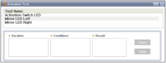
| 5. |
If you want to check each module operation forcefully, select "Actuation test".
|
Description BSD is a system that uses two magnetic wave radar sensors attached on the rear bumper to measure the distance from the following vehicles and provides the sensing and (visual and auditory) alarm of any vehicle coming into the blind spot.
Circuit Diagram
Other information:
Kia Cadenza YG 2016-2021 Service Manual: Description and Operation
Description Adaptive Front-lighting System (AFLS) AFLS(Adaptive Front-lighting System)is a headlamp orientation control system that takes into account both steering angle and vehicle speed to orient the headlamps to an angle that provides better nighttime visibility.
Kia Cadenza YG 2016-2021 Service Manual: Climate Control Air Filtar Repair procedures
Replacement 1. Disconnect the damper (B) from the glove box (A) and then remove the glove box lift (C). 2. Remove the filter cover (A) with pushing the knob. 3. Replace the air filter (B), install it after making sure of the direction of air filter.
Categories
- Manuals Home
- Kia Cadenza Owners Manual
- Kia Cadenza Service Manual
- Emission Control System
- Suspension System
- Timing Chain Repair procedures
- New on site
- Most important about car
