Kia Cadenza YG: Cylinder Block / Cylinder Block Repair procedures
Kia Cadenza YG 2016-2021 Service Manual / Engine Mechanical System / Cylinder Block / Cylinder Block Repair procedures
| Disassembly |
|

|

| 1. |
Remove the engine assembly from the vehicle.
(Refer to Engine And Transmission Assembly - "Engine And Transmission Assembly") |
| 2. |
Remove the transaxle assembly from the engine assembly.
(Refer to Automatic Transaxle System - "Automatic Transaxle") |
| 3. |
Remove the drive plate and adapter plate.
(Refer to Cylinder Block - "Drive Plate") |
| 4. |
Remove the rear oil seal case.
(Refer to Cylinder Bolck - "Rear Oil Seal") |
| 5. |
Install the engine to engine stand for disassembly. |
| 6. |
Remove the exhaust manifold.
(Refer to Intake And Exhaust System - "Exhaust Manifold") |
| 7. |
Remove the intake manifold.
(Refer to Intake And Exhaust System - "Intake Manifold") |
| 8. |
Remove the timing chain.
(Refer to Timing System - "Timing Chain") |
| 9. |
Remove the water temperature control assembly.
(Refer to Cooling System - "Water Temperature Control Aassembly") |
| 10. |
Remove the cylinder head.
(Refer to Cylinder Head Assembly - "Cylinder Head") |
| 11. |
Remove the oil pump.
(Refer to Lubrication System - "Oil Pump") |
| 12. |
Remove the oil filter body.
(Refer to Lubrication System - "Oil filter body") |
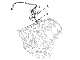
| 13. |
Remove the oil cover (A) and gasket (B).
|
| 14. |
Remove the water jacket seperator.
(Refer to Cylinder Block - "Water Jacket Seperator") |
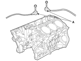
| 15. |
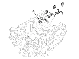
Remove the knock sensor (A).
|
| 16. |
Remove the upper oil pan.
(Refer to Lubrication System - "Oil Pan") |
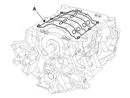
| 17. |
Remove the baffle plate (A).
|
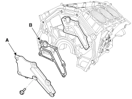
| 18. |
Remove the oil drain cover (A) and gasket (B).
|
| 19. |
Check the connecting rod end play.
(Refer to Cylinder Block - "Piston and Connecting Rod") |
| 20. |
Check the connecting rod cap oil clearance.
(Refer to Cylinder Block - "Piston and Connecting Rod") |
| 21. |
Remove the piston and connecting rod assemblies.
(Refer to Cylinder Block - "Piston and Connecting Rod") |
| 22. |
Remove the crankshaft main bearing cap and check oil clearance.
(Refer to Cylinder Block - "Crankshaft") |
| 23. |
Check the crankshaft end play.
(Refer to Cylinder Block - "Crankshaft") |
| 24. |
Remove the crankshaft.
(Refer to Cylinder Block - "Crankshaft") |
| 25. |
Remove the oil jets (A).
|
| Inspection |
Cylinder Block
| 1. |
Remove the gasket material.
Using a gasket scraper, remove all the gasket material from the top surface of the cylinder block. |
| 2. |
Clean the cylinder block
Using a soft brush and solvent, thoroughly clean the cylinder block. |
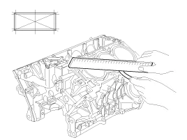
| 3. |
Inspect the top surface of the cylinder block for flatness.
Using a precision straight edge and feeler gauge, measure the surface contacting the cylinder head gasket for warpage.
|
| 4. |
Inspect cylinder bore diameter
Visually check the cylinder for vertical scratchs.
If deep scratches are present, replace the cylinder block. |
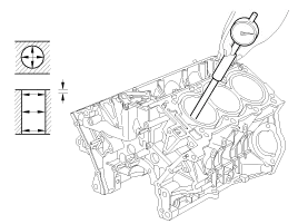
| 5. |
Inspect cylinder bore diameter
Using a cylinder bore gauge, measure the cylinder bore diameter at position in the thrust and axial directions.
|
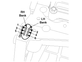
| 6. |
Check the cylinder bore size code on the cylinder block.
|
Boring Cylinder
| 1. |
Oversize pistons should be selected according to the largest bore cylinder.
|
| 2. |
Measure the outside diameter of the piston to be used. |
| 3. |
According to the measured O.D(Outer Diameter), calculate the new bore size.
|
| 4. |
Bore each of the cylinders to the calculated size.
|
| 5. |
Hone the cylinders, finishing them to the proper dimension (piston outside diameter + gap with cylinder). |
| 6. |
Check the clearance between the piston and cylinder.
|
| Reassembly |
| 1. |
Install the oil jets (A).
|
| 2. |
Install the crankshaft.
(Refer to Cylinder Block - "Crankshaft") |
| 3. |
Install the crankshaft main bearing cap and check oil clearance.
(Refer to Cylinder Block - "Crankshaft") |
| 4. |
Check the crankshaft end play.
(Refer to Cylinder Block - "Crankshaft") |
| 5. |
Install the piston and connecting rod assemblies.
(Refer to Cylinder Block - "Piston and Connecting Rod") |
| 6. |
Check the connecting rod end play.
(Refer to Cylinder Block - Piston and Connecting Rod") |
| 7. |
Install the oil drain cover(A) with a new gasket (B).
|
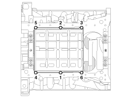
| 8. |
Install the baffle plate.
Install and uniformly tighten the baffle plate bolts, in several passes, in the sequence shown.
|
| 9. |
Install the upper oil pan.
(Refer to Lubrication System - "Oil Pan") |
| 10. |
Install the knock sensor (A).
|
| 11. |
Install the water jacket seperator.
(Refer to Cylinder Block - "Water Jacket Seperator") |
| 12. |
Remove the oil cover (A) and gasket (B).
|
| 13. |
Assemble the other parts in the reverse order of disassembly.
|
Disassembly • Use fender covers to avoid damaging painted surfaces. • To avoid damage, unplug the wiring connectors carefully while holding the connector portion.
Other information:
Kia Cadenza YG 2016-2021 Service Manual: Components and Components Location
C
Kia Cadenza YG 2016-2021 Service Manual: Troubleshooting
Troubleshooting Problem Symptoms Table Before replacing or repairing air conditioning components, first determine if the malfunction is due to the refrigerant charge, air flow or compressor. Use the table below to help you find the cause of the problem.
Categories
- Manuals Home
- Kia Cadenza Owners Manual
- Kia Cadenza Service Manual
- Specifications
- Body (Interior and Exterior)
- Battery Troubleshooting
- New on site
- Most important about car

Copyright © 2026 www.kcadenzavg.com - 0.0238