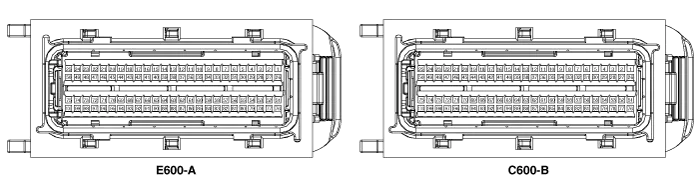
Kia Cadenza YG: Engine Control System / Engine Control Module (ECM) Schematic Diagrams
| ECM Terminal And Input/Output signal |
| ECM Terminal Function |
| Pin No. | Description | Connected to |
| 1 | - | |
| 2 | - | |
| 3 | - | |
| 4 | Immobilizer Lamp control output | Immobilizer Lamp [Without Button Engine Start System] |
| 5 | Power ground | Chassis Ground |
| 6 | Power ground | Chassis Ground |
| 7 | - | |
| 8 | - | |
| 9 | 2nd CAN [High] | Multi-Purpose Check Connector |
| 10 | CAN [High] | Other control module, Data Link Connector (DLC), Multi-Purpose Check Connector |
| 11 | Fuel Tank Pressure Sensor (FTPS) signal input | Fuel Tank Pressure Sensor (FTPS) |
| 12 | Electrical Load signal input | Head Lamp Relay |
| 13 | - | |
| 14 | Sensor power (+5V) | Accelerator Position Sensor (APS) 1 |
| 15 | Sensor power (+5V) | A/C Pressure Transducer (APT) |
| Rail Pressure Sensor (RPS) | ||
| 16 | Fuel Level Sender (FLS) signal input | Fuel Level Sender (FLS) |
| 17 | - | |
| 18 | - | |
| 19 | - | |
| 20 | A/C Compressor relay signal output | A/C Control Module |
| 21 | Brake Switch 2 signal input | Brake Switch |
| 22 | - | |
| 23 | - | |
| 24 | Alternator PWM signal input [FR] | Alternator |
| 25 | - | |
| 26 | - | |
| 27 | Battery power (B+) | Ignition Switch |
| 28 | Rail Pressure Sensor (RPS) signal input | Rail Pressure Sensor (RPS) |
| 29 | - | |
| 30 | Power ground | Chassis Ground |
| 31 | - | |
| 32 | - | |
| 33 | - | |
| 34 | 2nd CAN [Low] | Multi-Purpose Check Connector |
| 35 | CAN [Low] | Other control module, Data Link Connector (DLC), Multi-Purpose Check Connector |
| 36 | - | |
| 37 | Sensor ground | Rail Pressure Sensor (RPS) |
| 38 | Accelerator Position Sensor (APS) 1 signal input | Accelerator Position Sensor (APS) 1 |
| 39 | - | |
| 40 | - | |
| 41 | - | |
| 42 | A/C Switch "ON" signal input | A/C Control Module |
| 43 | Brake Switch 1 signal input | Brake Switch |
| 44 | - | |
| 45 | - | |
| 46 | - | |
| 47 | - | |
| 48 | - | |
| 49 | - | |
| 50 | - | |
| 51 | - | |
| 52 | Battery power (B+) | Battery |
| 53 | - | |
| 54 | - | |
| 55 | Power ground | Chassis Ground |
| 56 | - | |
| 57 | A/C Compressor Clutch Relay control output | A/C Control Module [With Immobilzer] |
| 58 | - | |
| 59 | Sensor ground | Accelerator Position Sensor (APS) 2 |
| 60 | Sensor ground | Accelerator Position Sensor (APS) 1 |
| 61 | Sensor ground | Fuel Tank Pressure Sensor (FTPS) |
| 62 | Ground | Cruise Control Switch |
| 63 | Sensor ground | A/C Pressure Transducer (APT) |
| 64 | - | |
| 65 | Sensor Power (+5V) | Fuel Tank Pressure Sensor (FTPS) |
| 66 | Cruise Control Switch signal input | Cruise Control Switch |
| 67 | A/C Pressure Transducer (APT) signal input | A/C Pressure Transducer (APT) |
| 68 | Accelerator Position Sensor (APS) 2 signal input | Accelerator Position Sensor (APS) 2 |
| 69 | - | |
| 70 | Engine speed signal output | Power Distribution Module (PDM) |
| 71 | Cooling Fan Relay [High] control output | Cooling Fan Relay [High] |
| 72 | Alternator PWM signal output (COM) | Alternator |
| 73 | - | |
| 74 | Immobilizer communication line | Smart Key Control Module [With Button Engine Start System] |
| Immobilizer Control Unit [Without Button Engine Start System] | ||
| 75 | Battery power (B+) | Main Relay |
| 76 | - | |
| 77 | Battery power (B+) | Battery |
| 78 | - | |
| 79 | - | |
| 80 | Power ground | Chassis ground |
| 81 | - | |
| 82 | - | |
| 83 | - | |
| 84 | - | |
| 85 | - | |
| 86 | - | |
| 87 | LIN (Local Interconnect Network) Serial Bus Line | Battery Sensor |
| 88 | - | |
| 89 | - | |
| 90 | Sensor power (+5V) | Accelerator Position Sensor (APS) 2 |
| 91 | Cooling Fan Relay [Low] control output | Cooling Fan Relay [Low] |
| 92 | - | |
| 93 | Starter Relay control output | Starter Relay |
| 94 | Main Relay control output | Main Relay |
| 95 | Fuel pump Relay control output | Fuel pump Relay |
| 96 | Canister Close Valve (CCV) control output | Canister Close Valve (CCV) |
| 97 | - | |
| 98 | - | |
| 99 | Battery power (B+) | Main Relay |
| 100 | Battery power (B+) | Main Relay |
| Pin No. | Description | Connected to |
| 1 | - | |
| 2 | - | |
| 3 | - | |
| 4 | - | |
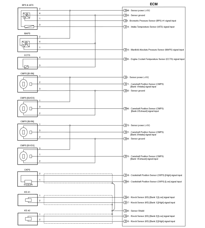
| 5 | Sensor power (+5V) | Camshaft Position Sensor (CMPS) [Bank 1/Intake] |
| Camshaft Position Sensor (CMPS) [Bank 2/Exhaust] | ||
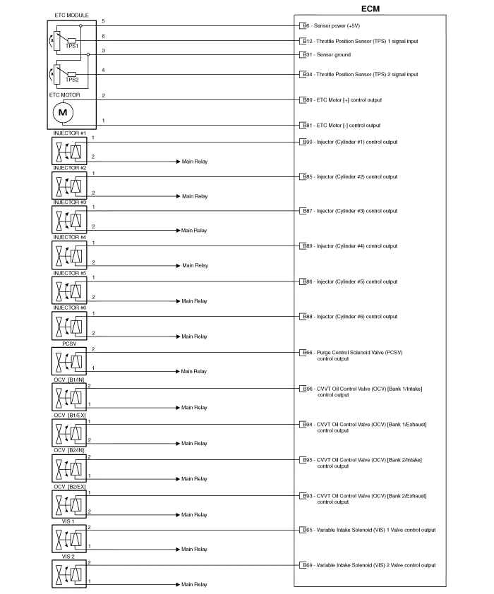
| 6 | Sensor power (+5V) | Throttle Position Sensor (TPS) |
| 7 | - | |
| 8 | Crank request signal output | Power Distribution Module (PDM) [With Button Engine Start System] |
| Ignition Switch [Without Button Engine Start System] | ||
| 9 | Barometric Pressure Sensor (BPS) signal input | Barometric Pressure Sensor (BPS) |
| 10 | CVVT Oil Temperature Sensor (OTS) signal input | CVVT Oil Temperature Sensor (OTS) |
| 11 | A/C Blower “MAX” signal input | A/C Control Module |
| 12 | Throttle Position Sensor (TPS) 1 signal input | Throttle Position Sensor (TPS) 1 |
| 13 | Manifold Absolute Pressure Sensor (MAPS) signal input | Manifold Absolute Pressure Sensor (MAPS) |
| 14 | Intake Air Temperature Sensor (IATS) signal input | Intake Air Temperature Sensor (IATS) |
| 15 | Vehicle speed signal input | Power Distribution Module (PDM) [With Button Engine Start System] |
| ABS/ESP Control Module [Without Button Engine Start System] | ||
| 16 | Knock Sensor (KS) [Bank 2] [High] signal input | Knock Sensor (KS) [Bank 2] |
| 17 | Knock Sensor (KS) [Bank 1] [High] signal input | Knock Sensor (KS) [Bank 1] |
| 18 | Crankshaft Position Sensor (CKPS) [High] signal input | Crankshaft Position Sensor (CKPS) |
| 19 | Sensor ground | CVVT Oil Temperature Sensor (OTS) |
| 20 | - | |
| 21 | Camshaft Position Sensor (CMPS) [Bank 2/Intake] signal input | Camshaft Position Sensor (CMPS) [Bank 2/Intake] |
| 22 | - | |
| 23 | - | |
| 24 | Ignition Coil (Cylinder #1) control output | Ignition Coil (Cylinder #1) |
| 25 | - | |
| 26 | - | |
| 27 | - | |
| 28 | - | |
| 29 | - | |
| 30 | - | |
| 31 | Sensor ground | Throttle Position Sensor (TPS) 1 |
| 32 | Sensor ground | Camshaft Position Sensor (CMPS) [Bank 1/Intake] |
| Camshaft Position Sensor (CMPS) [Bank 2/Exhaust] | ||
| 33 | Sensor ground | Heated Oxygen Sensor (HO2S) [Bank 2/Sensor 2] |
| 34 | Throttle Position Sensor (TPS) 2 signal input | Throttle Position Sensor (TPS) 2 |
| 35 | Engine Coolant Temperature Sensor (ECTS) signal input | Engine Coolant Temperature Sensor (ECTS) |
| 36 | - | |
| 37 | - | |
| 38 | Heated Oxygen Sensor (HO2S) [Bank 1/Sensor 1] signal input | Heated Oxygen Sensor (HO2S) [Bank 1/Sensor 1] |
| 39 | Sensor ground | Heated Oxygen Sensor (HO2S) [Bank 1/Sensor 1] |
| 40 | Sensor Shield | Crankshaft Position Sensor (CKPS) |
| Knock Sensor (KS) #1 [Bank 1] | ||
| Knock Sensor (KS) #2 [Bank 2] | ||
| 41 | Knock Sensor (KS) [Bank 2] [Low] signal input | Knock Sensor (KS) [Bank 2] |
| 42 | Knock Sensor (KS) [Bank 1] [Low] signal input | Knock Sensor (KS) [Bank 1] |
| 43 | Crankshaft Position Sensor (CKPS) [Low] signal input | Crankshaft Position Sensor (CKPS) |
| 44 | Sensor ground | Camshaft Position Sensor (CMPS) [Bank 1/Exhaust] |
| Camshaft Position Sensor (CMPS) [Bank 2/Intake] | ||
| 45 | - | |
| 46 | Camshaft Position Sensor (CMPS) [Bank 2/Exhaust] signal input | Camshaft Position Sensor (CMPS) [Bank 2/Exhaust] |
| 47 | - | |
| 48 | Sensor power (+5V) | Barometric Pressure Sensor (BPS) |
| Manifold Absolute Pressure Sensor (MAPS) | ||
| VCM Position Sensor | ||
| 49 | Ignition Coil (Cylinder #3) control output | Ignition Coil (Cylinder #3) |
| 50 | - | |
| 51 | - | |
| 52 | - | |
| 53 | - | |
| 54 | - | |
| 55 | - | |
| 56 | Sensor ground | Barometric Pressure Sensor (BPS) |
| Manifold Absolute Pressure Sensor (MAPS) | ||
| Engine Coolant Temperature Sensor (ECTS) | ||
| 57 | - | |
| 58 | Heated Oxygen Sensor (HO2S) [Bank 2/Sensor 2] signal input | Heated Oxygen Sensor (HO2S) [Bank 2/Sensor 2] |
| 59 | Heated Oxygen Sensor (HO2S) [Bank 1/Sensor 2] signal input | Heated Oxygen Sensor (HO2S) [Bank 1/Sensor 2] |
| 60 | Sensor ground | Heated Oxygen Sensor (HO2S) [Bank 1/Sensor 2] |
| 61 | - | |
| 62 | - | |
| 63 | Heated Oxygen Sensor (HO2S) [Bank 2/Sensor 1] signal input | Heated Oxygen Sensor (HO2S) [Bank 2/Sensor 1] |
| 64 | Sensor ground | Heated Oxygen Sensor (HO2S) [Bank 2/Sensor 1] |
| 65 | Variable Intake Solenoid (VIS) Valve 1 control output | Variable Intake Solenoid (VIS) Valve 1 |
| 66 | Purge Control Solenoid Valve (PCSV) control output | Purge Control Solenoid Valve (PCSV) |
| 67 | - | |
| 68 | - | |
| 69 | Variable Intake Solenoid (VIS) Valve 2 control output | Variable Intake Solenoid (VIS) Valve 2 |
| 70 | Camshaft Position Sensor (CMPS) [Bank 1/Exhaust] signal input | Camshaft Position Sensor (CMPS) [Bank 1/Exhaust] |
| 71 | Camshaft Position Sensor (CMPS) [Bank 1/Intake] signal input | Camshaft Position Sensor (CMPS) [Bank 1/Intake] |
| 72 | - | |
| 73 | Sensor Power (+5V) | Camshaft Position Sensor (CMPS) [Bank 1/Exhaust] |
| Camshaft Position Sensor (CMPS) [Bank 2/Intake] | ||
| 74 | Ignition Coil (Cylinder #5) control output | Ignition Coil (Cylinder #5) |
| 75 | - | |
| 76 | - | |
| 77 | - | |
| 78 | - | |
| 79 | - | |
| 80 | ETC Motor [+] control output | ETC Motor |
| 81 | ETC Motor [-] control output | ETC Motor |
| 82 | Heated Oxygen Sensor (HO2S) [Bank 1/Sensor 2] Heater control output | Heated Oxygen Sensor (HO2S) [Bank 1/Sensor 2] |
| 83 | Heated Oxygen Sensor (HO2S) [Bank 2/Sensor 2] Heater control output | Heated Oxygen Sensor (HO2S) [Bank 2/Sensor 2] |
| 84 | Fuel Pressure Control Valve (FPCV) control output | Injector Drive Box (IDB) |
| 85 | Injector (Cylinder #2) control output | Injector Drive Box (IDB) |
| 86 | Injector (Cylinder #5) control output | Injector Drive Box (IDB) |
| 87 | Injector (Cylinder #3) control output | Injector Drive Box (IDB) |
| 88 | Injector (Cylinder #6) control output | Injector Drive Box (IDB) |
| 89 | Injector (Cylinder #4) control output | Injector Drive Box (IDB) |
| 90 | Injector (Cylinder #1) control output | Injector Drive Box (IDB) |
| 91 | Heated Oxygen Sensor (HO2S ) [Bank 1/Sensor 1] Heater control output | Heated Oxygen Sensor (HO2S) [Bank 1/Sensor 1] |
| 92 | Heated Oxygen Sensor (HO2S) [Bank 2/Sensor 1] Heater control output | Heated Oxygen Sensor (HO2S) [Bank 2/Sensor 1] |
| 93 | CVVT Oil Control Valve (OCV) [Bank 2/Exhaust] control output | CVVT Oil Control Valve (OCV) [Bank 2/Exhaust] |
| 94 | CVVT Oil Control Valve (OCV) [Bank 1/Exhaust] control output | CVVT Oil Control Valve (OCV) [Bank 1/Exhaust] |
| 95 | CVVT Oil Control Valve (OCV) [Bank 2/Intake] control output | CVVT Oil Control Valve (OCV) [Bank 2/Intake] |
| 96 | CVVT Oil Control Valve (OCV) [Bank 1/Intake] control output | CVVT Oil Control Valve (OCV) [Bank 1/Intake] |
| 97 | Ignition Coil (Cylinder #2) control output | Ignition Coil (Cylinder #2) |
| 98 | Ignition Coil (Cylinder #6) control output | Ignition Coil (Cylinder #6) |
| 99 | Ignition Coil (Cylinder #4) control output | Ignition Coil (Cylinder #4) |
| 100 | - | |
| ECM Terminal Input/Output Signal |
| Pin No. | Description | Condition | Type | Level |
| 1 | - | | | |
| 2 | - | | | |
| 3 | - | | | |
| 4 | Immobilizer Lamp control output | Lamp OFF | DC | Battery Voltage |
| Lamp ON | Max. 1.1V | |||
| 5 | Power ground | Idle | DC | Max. 0.1V |
| 6 | Power ground | Idle | DC | Max. 0.1V |
| 7 | - | | | |
| 8 | - | | | |
| 9 | 2nd CAN [High] | Recessive | Pulse | 2.0 ~ 3.0V |
| Dominant | 2.75 ~ 4.5V | |||
| 10 | CAN [High] | Recessive | Pulse | 2.0 ~ 3.0V |
| Dominant | 2.75 ~ 4.5V | |||
| 11 | Fuel Tank Pressure Sensor (FTPS) signal input | Idle | Analog | 0.4 ~ 4.6V |
| 12 | Electrical Load signal input | Head Lamp OFF | DC | Battery Voltage |
| Head Lamp ON | Max. 1.0V | |||
| 13 | - | | | |
| 14 | Sensor power (+5V) | IG OFF | DC | Max. 0.5V |
| IG ON | 4.9 ~ 5.1V | |||
| 15 | Sensor power (+5V) | IG OFF | DC | Max. 0.5V |
| IG ON | 4.9 ~ 5.1V | |||
| 16 | Fuel Level Sender (FLS) signal input | IG ON | Analog | 0.88 ~ 8.45V |
| 17 | - | | | |
| 18 | - | | | |
| 19 | - | | | |
| 20 | A/C Compressor relay signal output | A/C OFF | DC | Max. 1.0V |
| A/C ON | Battery Voltage | |||
| 21 | Brake Switch 2 signal input | Brake OFF | DC | Battery Voltage |
| Brake ON | Max. 0.5V | |||
| 22 | - | | | |
| 23 | - | | | |
| 24 | Alternator PWM signal input [FR] | Idle | PWM | High: Battery Voltage |
| Low: Max. 2.0V | ||||
| 133 | ||||
| 5 | ||||
| 25 | - | |||
| 26 | - | | | |
| 27 | Battery power (B+) | IG OFF | DC | Battery Voltage |
| IG ON | Max. 1.0V | |||
| 28 | Rail Pressure Sensor (RPS) signal input | Idle | DC | 1.0 ~ 2.0V |
| 29 | - | | | |
| 30 | Power ground | Idle | DC | Max. 0.1V |
| 31 | - | | | |
| 32 | - | | | |
| 33 | - | | | |
| 34 | 2nd CAN [Low] | Recessive | Pulse | 2.0 ~ 3.0V |
| Dominant | 0.5 ~ 2.25V | |||
| 35 | CAN [Low] | Recessive | Pulse | 2.0 ~ 3.0V |
| Dominant | 0.5 ~ 2.25V | |||
| 36 | - | | | |
| 37 | Sensor ground | Idle | DC | Max. 0.1V |
| 38 | Accelerator Position Sensor (APS) 1 signal input | C.T | Analog | 0.7 ~ 0.8V |
| W.O.T | 3.85 ~ 4.35V | |||
| 39 | - | | | |
| 40 | - | | | |
| 41 | - | |||
| 42 | A/C Switch "ON" signal input | A/C OFF | DC | Max. 1.0V |
| A/C ON | Battery Voltage | |||
| 43 | Brake Switch 1 signal input | Brake OFF | DC | Max. 0.5V |
| Brake ON | Battery Voltage | |||
| 44 | - | | | |
| 45 | - | | | |
| 46 | - | | | |
| 47 | - | | | |
| 48 | - | |||
| 49 | - | | | |
| 50 | - | | | |
| 51 | - | | | |
| 52 | Battery power (B+) | Always (Without Ignition key) | DC | Battery Voltage |
| 53 | - | | | |
| 54 | - | | | |
| 55 | Power ground | Idle | DC | Max. 0.1V |
| 56 | - | | | |
| 57 | Fuel Pump Relay control output [Without Immobilzer] | Relay OFF | DC | Battery Voltage |
| A/C Compressor Clutch Relay control output [With Immobilzer] | Relay ON | Max 1.1V | ||
| 58 | - | | | |
| 59 | Sensor ground | Idle | DC | Max. 0.1V |
| 60 | Sensor ground | Idle | DC | Max. 0.1V |
| 61 | Sensor ground | Idle | DC | Max. 0.1V |
| 62 | Ground | Idle | DC | Max. 0.1V |
| 63 | Sensor ground | Idle | DC | Max. 0.1V |
| 64 | - | | | |
| 65 | Sensor Power (+5V) | IG OFF | DC | Max. 0.5V |
| IG ON | 4.75 ~ 5.25V | |||
| 66 | Cruise Control Switch signal input | “MAIN” | Analog | 11.1 ~ 12.1V |
| “SET” | 1.0 ~ 1.8V | |||
| “CANCEL” | -0.5 ~ 0.5V | |||
| “RESUME” | 2.5 ~ 3.5V | |||
| 67 | A/C Pressure Transducer (APT) signal input | A/C ON | Analog | 0.5 ~ 4.5V |
| 68 | Accelerator Position Sensor (APS) 2 signal input | C.T | Analog | 0.29 ~ 0.46V |
| W.O.T | 1.93 ~ 2.18V | |||
| 69 | - | |||
| 70 | Engine speed signal output | Engine Running | Pulse | High: Battery Voltage |
| Low: Max. 1.1V | ||||
| 0 | ||||
| 47.5 | ||||
| 71 | Cooling Fan Relay [High] control output | A/C ON | Pulse | High: Battery Voltage |
| Low: Max. 1.1V | ||||
| 72 | Alternator PWM signal output (COM) | IG ON | PWM | High: Min. 4.0V |
| Low: Max. 2.0V | ||||
| Frequency = 125Hz | ||||
| 73 | - | | | |
| 74 | Immobilizer communication line | Transmitting | DC | High: Min. Vbatt X 80% |
| Low: Max. Vbatt X 20% | ||||
| Receiving | High: Min. Vbatt X 70% | |||
| Low: Max. Vbatt X 30% | ||||
| 75 | Battery power (B+) | IG OFF | DC | Battery Voltage |
| IG ON | Max. 1.0V | |||
| 76 | - | | | |
| 77 | Battery power (B+) | Always (Without Ignition key) | DC | Battery Voltage |
| 78 | - | |||
| 79 | - | | | |
| 80 | Power ground | Idle | DC | Max. 0.1V |
| 81 | - | | | |
| 82 | - | | | |
| 83 | - | | | |
| 84 | - | | | |
| 85 | - | | | |
| 86 | - | | | |
| 87 | LIN (Local Interconnect Network) Serial Bus Line | Transmitting | DC | High: Min. Vbatt X 80% |
| Low: Max. Vbatt X 20% | ||||
| Receiving | High: Min. Vbatt X 70% | |||
| Low: Max. Vbatt X 30% | ||||
| 88 | - | | | |
| 89 | - | | | |
| 90 | Sensor power (+5V) | IG OFF | DC | Max. 0.5V |
| IG ON | 4.75 ~ 5.25V | |||
| 91 | Cooling Fan Relay [Low] control output | A/C ON | Pulse | High: Battery Voltage |
| Low: Max. 1.1V | ||||
| 92 | - | | | |
| 93 | Starter Relay control output | Relay OFF | DC | Battery Voltage |
| Relay ON | Max 1.1V | |||
| 94 | Main Relay control output | Relay OFF | DC | Battery Voltage |
| Relay ON | Max 1.7V | |||
| 95 | Fuel Pump Relay control output | Relay OFF | DC | Battery Voltage |
| Relay ON | Max 1.1V | |||
| 96 | Canister Close Valve (CCV) control output | Active | Pulse | High: Battery Voltage |
| Inactive | Low: Max. 1.0V | |||
| | Vpeak: Max. 70V | |||
| 97 | - | | | |
| 98 | - | | | |
| 99 | Battery power (B+) | IG OFF | DC | Battery Voltage |
| IG ON | Max. 1.0V | |||
| 100 | Battery power (B+) | IG OFF | DC | Battery Voltage |
| IG ON | Max. 1.0V |
| Pin No. | Description | Condition | Type | Level |
| 1 | - | | | |
| 2 | Variable Charge Motion Actuator (VCMA) PWM output | Engine Running | PWM | High: Battery Voltage |
| Low: 1.1V | ||||
| 3 | - | | | |
| 4 | - | | | |
| 5 | Sensor power (+5V) | IG OFF | DC | Max. 0.5V |
| IG ON | 4.75 ~ 5.25V | |||
| 6 | Sensor power (+5V) | IG OFF | DC | Max. 0.5V |
| IG ON | 4.75 ~ 5.25V | |||
| 7 | Throttle Position Sensor PWM signal output | | | |
| 8 | Crank request signal output | S/W OFF | DC | Max. 1.0V |
| S/W ON | Battery Voltage | |||
| 9 | Barometric Pressure Sensor (BPS) signal input | IG ON | Analog | Approx. 4.0V |
| 10 | CVVT Oil Temperature Sensor (OTS) signal input | IG ON | Analog | 3.2V at -40°C(-40°F) |
| 0.1V at 150°C(302°F) | ||||
| 11 | A/C Blower “MAX” signal input | IG ON | DC | High: Battery Voltage |
| Low: 0V | ||||
| 12 | Throttle Position Sensor (TPS) 1 signal input | C.T | Analog | 0.25 ~ 0.9V |
| W.O.T | Min. 4.0V | |||
| 13 | Manifold Absolute Pressure Sensor (MAPS) signal input | IG ON | Analog | Approx. 4.44V |
| Idle | Approx. 0.75V | |||
| 14 | Intake Air Temperature Sensor (IATS) signal input | IG ON | Analog | 3.2V at -40°C(-40°F) |
| 0.05V at 125°C(257°F) | ||||
| 15 | Vehicle speed signal input | Vehicle Running | Pulse | High: Battery Voltage |
| Low: Max. 0.5V | ||||
| 0.7(1kph) | ||||
| 44 | ||||
| 16 | Knock Sensor (KS) [Bank 2] [High] signal input | Knocking | Variable | -0.3 ~ 0.3V |
| Normal | Frequency | 0V | ||
| 17 | Knock Sensor (KS) [Bank 1] [High] signal input | Knocking | Variable | -0.3 ~ 0.3V |
| Normal | Frequency | 0V | ||
| 18 | Crankshaft Position Sensor (CKPS) [High] signal input | Idle | SINE | 0.4 |
| Wave | 55 | |||
| 19 | Sensor ground | Idle | DC | Max. 0.1V |
| 20 | - | |||
| 21 | Camshaft Position Sensor (CMPS) [Bank 2/Intake] signal input | Idle | Pulse | High: 3.2 ~ Vcc |
| Low: Max. 0.7V | ||||
| 0 | ||||
| 22 | - | | | |
| 23 | - | | | |
| 24 | Ignition Coil (Cylinder #1) control output | Engine Running | Pulse | Vpeak = 400V |
| 0 | ||||
| 25 | - | | | |
| 26 | - | | | |
| 27 | - | | | |
| 28 | - | | | |
| 29 | - | | | |
| 30 | - | | | |
| 31 | Sensor ground | Idle | DC | Max. 0.1V |
| 32 | Sensor ground | Idle | DC | Max. 0.1V |
| 33 | Sensor ground | Idle | DC | Max. 0.1V |
| 34 | Throttle Position Sensor (TPS) 2 signal input | C.T | Analog | Min. 4.0V |
| W.O.T | 0.25 ~ 0.9V | |||
| 35 | Engine Coolant Temperature Sensor (ECTS) signal input | IG ON | Analog | 3.22V at -40°C(-40°F) |
| 0.29V at 125°C(257°F) | ||||
| 36 | - | | | |
| 37 | - | | | |
| 38 | Heated Oxygen Sensor (HO2S) [Bank 1/Sensor 1] signal input | RICH | Analog | Min. 0.8V |
| LEAN | Max. 0.1V | |||
| 39 | Sensor ground | Idle | DC | Max. 0.1V |
| 40 | Sensor Shield | Idle | DC | Max. 0.1V |
| 41 | Knock Sensor (KS) [Bank 2] [Low] signal input | Knocking | Variable | -0.3 ~ 0.3V |
| Normal | Frequency | 0V | ||
| 42 | Knock Sensor (KS) [Bank 1] [Low] signal input | Knocking | Variable | -0.3 ~ 0.3V |
| Normal | Frequency | 0V | ||
| 43 | Crankshaft Position Sensor (CKPS) [Low] signal input | Idle | SINE | 0.4 |
| Wave | 55 | |||
| 44 | Sensor ground | Idle | DC | Max. 0.1V |
| 45 | - | | | |
| 46 | Camshaft Position Sensor (CMPS) [Bank 2/Exhaust] signal input | Idle | Pulse | High: 3.2 ~ Vcc |
| Low: Max. 0.7V | ||||
| 0 | ||||
| 47 | - | | | |
| 48 | Sensor power (+5V) | IG OFF | DC | Max. 0.5V |
| IG ON | 4.75 ~ 5.25V | |||
| 49 | Ignition Coil (Cylinder #3) control output | Engine Running | Pulse | Vpeak = 400V |
| 0 | ||||
| 50 | - | | | |
| 51 | - | | | |
| 52 | - | | | |
| 53 | - | | | |
| 54 | - | | | |
| 55 | - | | | |
| 56 | Sensor ground | Idle | DC | Max. 0.1V |
| 57 | - | | | |
| 58 | Heated Oxygen Sensor (HO2S) [Bank 2/Sensor 2] signal input | RICH | Analog | Min. 0.8V |
| LEAN | Max. 0.1V | |||
| 59 | Heated Oxygen Sensor (HO2S) [Bank 1/Sensor 2] signal input | RICH | Analog | Min. 0.8V |
| LEAN | Max. 0.1V | |||
| 60 | Sensor ground | Idle | DC | Max. 0.1V |
| 61 | - | | | |
| 62 | - | | | |
| 63 | Heated Oxygen Sensor (HO2S) [Bank 2/Sensor 1] signal input | RICH | Analog | Min. 0.8V |
| LEAN | Max. 0.1V | |||
| 64 | Sensor ground | Idle | DC | Max. 0.1V |
| 65 | Variable Intake Solenoid (VIS) Valve 1 control output | Engine Running | PWM | High: Battery Voltage |
| Low: Max. 1.1V | ||||
| 66 | Purge Control Solenoid Valve (PCSV) control output | Engine Running | PWM | High: Battery Voltage |
| Low: Max. 1.0V | ||||
| 67 | - | | | |
| 68 | - | | | |
| 69 | Variable Intake Solenoid (VIS) Valve 2 control output | Engine Running | PWM | High: Battery Voltage |
| Low: Max. 1.1V | ||||
| 70 | Camshaft Position Sensor (CMPS) [Bank 1/Exhaust] signal input | Idle | Pulse | High: 3.2 ~ Vcc |
| Low: Max. 0.7V | ||||
| 0 | ||||
| 71 | Camshaft Position Sensor (CMPS) [Bank 1/Intake] signal input | Idle | Pulse | High: 3.2 ~ Vcc |
| Low: Max. 0.7V | ||||
| 0 | ||||
| 72 | - | | | |
| 73 | Sensor Power (+5V) | IG OFF | DC | Max. 0.5V |
| IG ON | 4.75 ~ 5.25V | |||
| 74 | Ignition Coil (Cylinder #5) control output | Engine Running | Pulse | Vpeak = 400V |
| 0 | ||||
| 75 | - | | | |
| 76 | - | | | |
| 77 | - | | | |
| 78 | - | | | |
| 79 | - | | | |
| 80 | ETC Motor [+] control output | Engine Running | PWM | High: Battery Voltage |
| Low: Max.1.0V | ||||
| 1,500 | ||||
| 0 | ||||
| 81 | ETC Motor [-] control output | Engine Running | PWM | High: Battery Voltage |
| Low: Max.1.0V | ||||
| 1,500 | ||||
| 0 | ||||
| 82 | Heated Oxygen Sensor (HO2S) [Bank 1/Sensor 2] Heater control output | Engine Running | PWM | High: Battery Voltage |
| Low: Max. 1.15V | ||||
| 0 | ||||
| 83 | Heated Oxygen Sensor (HO2S) [Bank 2/Sensor 2] Heater control output | Engine Running | PWM | High: Battery Voltage |
| Low: Max. 1.15V | ||||
| 0 | ||||
| 84 | Fuel Pressure Control Valve (FPCV) control output | | | |
| 85 | Injector (Cylinder #2) control output | Engine Running | PWM | High: Battery Voltage |
| Low: Max. 1.0V | ||||
| 0 | ||||
| 47 | ||||
| 86 | Injector (Cylinder #5) control output | Engine Running | PWM | High: Battery Voltage |
| Low: Max. 1.0V | ||||
| 0 | ||||
| 47 | ||||
| 87 | Injector (Cylinder #3) control output | Engine Running | PWM | High: Battery Voltage |
| Low: Max. 1.0V | ||||
| 0 | ||||
| 47 | ||||
| 88 | Injector (Cylinder #6) control output | Engine Running | PWM | High: Battery Voltage |
| Low: Max. 1.0V | ||||
| 0 | ||||
| 47 | ||||
| 89 | Injector (Cylinder #4) control output | Engine Running | PWM | High: Battery Voltage |
| Low: Max. 1.0V | ||||
| 0 | ||||
| 47 | ||||
| 90 | Injector (Cylinder #1) control output | Engine Running | PWM | High: Battery Voltage |
| Low: Max. 1.0V | ||||
| 0 | ||||
| 47 | ||||
| 91 | Heated Oxygen Sensor (HO2S ) [Bank 1/Sensor 1] Heater control output | Engine Running | PWM | High: Battery Voltage |
| Low: Max. 1.15V | ||||
| 0 | ||||
| 92 | Heated Oxygen Sensor (HO2S) [Bank 2/Sensor 1] Heater control output | Engine Running | PWM | High: Battery Voltage |
| Low: Max. 1.15V | ||||
| 0 | ||||
| 93 | CVVT Oil Control Valve (OCV) [Bank 2/Exhaust] control output | Engine Running | PWM | High: Battery Voltage |
| Low: Max. 1.0V | ||||
| Frequency = 128Hz | ||||
| 0 | ||||
| 94 | CVVT Oil Control Valve (OCV) [Bank 1/Exhaust] control output | Engine Running | PWM | High: Battery Voltage |
| Low: Max. 1.0V | ||||
| Frequency = 128Hz | ||||
| 0 | ||||
| 95 | CVVT Oil Control Valve (OCV) [Bank 2/Intake] control output | Engine Running | PWM | High: Battery Voltage |
| Low: Max. 1.0V | ||||
| Frequency = 128Hz | ||||
| 0 | ||||
| 96 | CVVT Oil Control Valve (OCV) [Bank 1/Intake] control output | Engine Running | PWM | High: Battery Voltage |
| Low: Max. 1.0V | ||||
| Frequency = 128Hz | ||||
| 0 | ||||
| 97 | Ignition Coil (Cylinder #2) control output | Engine Running | Pulse | Vpeak = 400V |
| 0 | ||||
| 98 | Ignition Coil (Cylinder #6) control output | Engine Running | Pulse | Vpeak = 400V |
| 0 | ||||
| 99 | Ignition Coil (Cylinder #4) control output | Engine Running | Pulse | Vpeak = 400V |
| 0 | ||||
| 100 | - | | | |
| Circuit Diagram |


Components Location 1. ECM (Engine Control Module)2. Barometric Pressure Sensor (BPS)3. Manifold Absolute Pressure Sensor (MAPS)4. Intake Air Temperature Sensor (IATS)5.
Removal When replacing the ECM, the vehicle equipped with the immobilizer must be performed procedure as below. [In the case of installing used ECM] 1) Perform "ECM Neutral mode" procedure with GDS.
Other information:
Kia Cadenza YG 2016-2021 Service Manual: Antenna Coil Repair procedures
Removal 1. Disconnect the negative (-) battery terminal. 2. Remove the crash pad lower panel. (Refer to Body - "Crash Pad") 3. Disconnect the 6P connector (B) of the coil antenna and then remove the coil antenna (A) after loosening the screw.
Kia Cadenza YG 2016-2021 Service Manual: Photo Sensor Repair procedures
Inspection 1. Ignition "ON" 2. Using the scan tool. 3. Emit intensive light toward photo sensor using a lamp, and check the output voltage change. 4. The voltage will rise with higher intensive light and reduce with lower intensive light.
Categories
- Manuals Home
- Kia Cadenza Owners Manual
- Kia Cadenza Service Manual
- Timing Chain Repair procedures
- Rail Pressure Sensor (RPS) Schematic Diagrams
- Restraint
- New on site
- Most important about car
